Vehicular air-conditioner

a technology for air conditioners and vehicles, applied in the direction of humidity control, refrigeration components, ratio control, etc., can solve the problems of insufficient heating capacity, immediate rise of humidity in the vehicle compartment, impaired passenger comfort, etc., to suppress the fogging of the window glass and suppress the drop in heating capacity

Inactive Publication Date: 2011-06-14
DENSO CORP
View PDF13 Cites 18 Cited by
  • Summary
  • Abstract
  • Description
  • Claims
  • Application Information

AI Technical Summary

Benefits of technology

[0008]An object of the present invention is to provide a vehicle air-conditioner designed to suppress fogging of the window glass and suppress a drop in the heating capacity.

Problems solved by technology

For this reason, the heating capacity becomes insufficient.
In particular, when heating in the outside air mode at the time of a low outside air temperature, the heating capacity will drop, the temperature inside the vehicle compartment will not rise, and passenger comfort will be impaired.
While the problem of the insufficient heating capacity can be eliminated, when setting the inside air mode, the humidity resulting from the respiration of the passengers causes the humidity in the vehicle compartment to immediately rise and ends up causing the front window glass to fog up.

Method used


Image

  • Vehicular air-conditioner
  • Vehicular air-conditioner
  • Vehicular air-conditioner

Examples


first embodiment

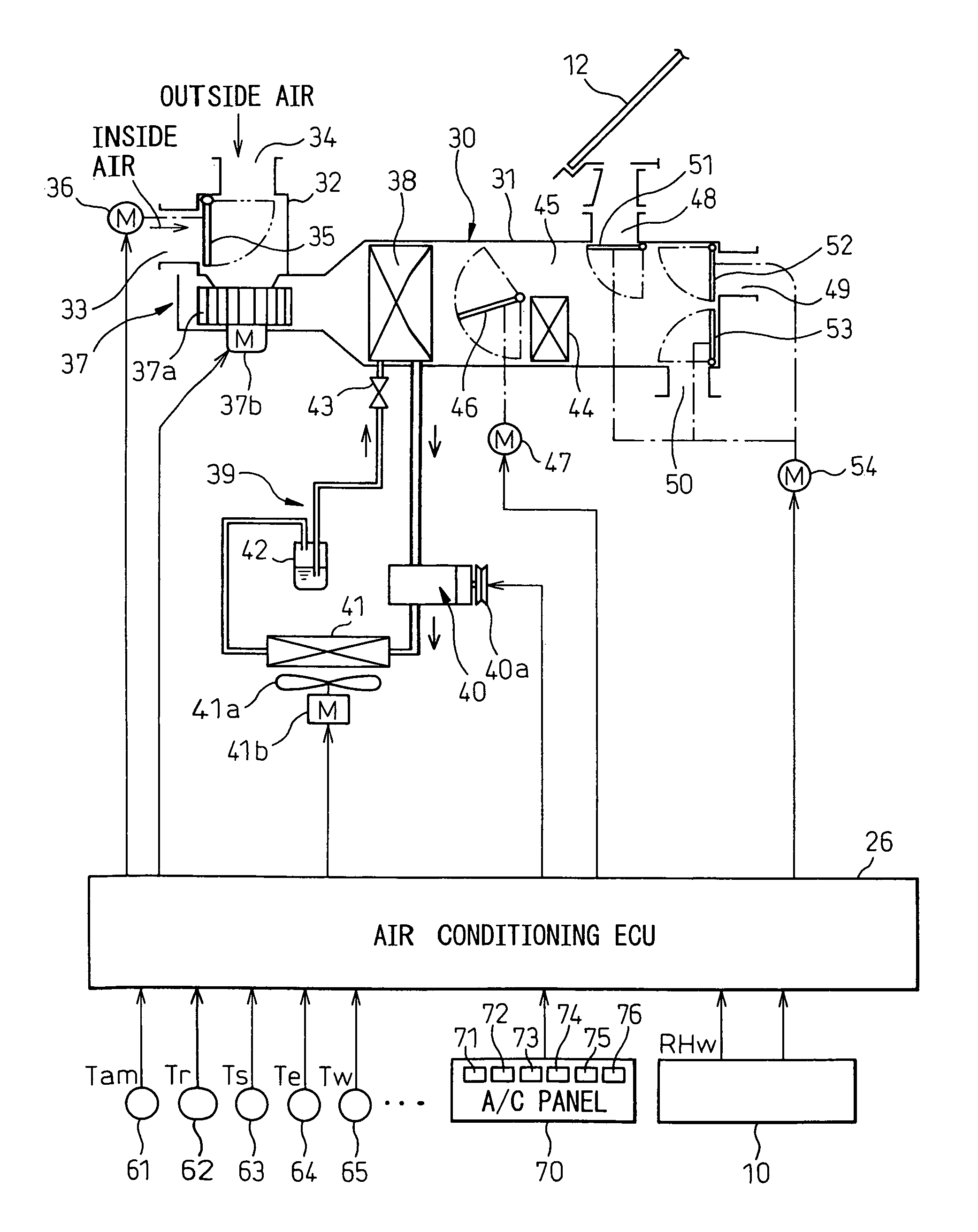
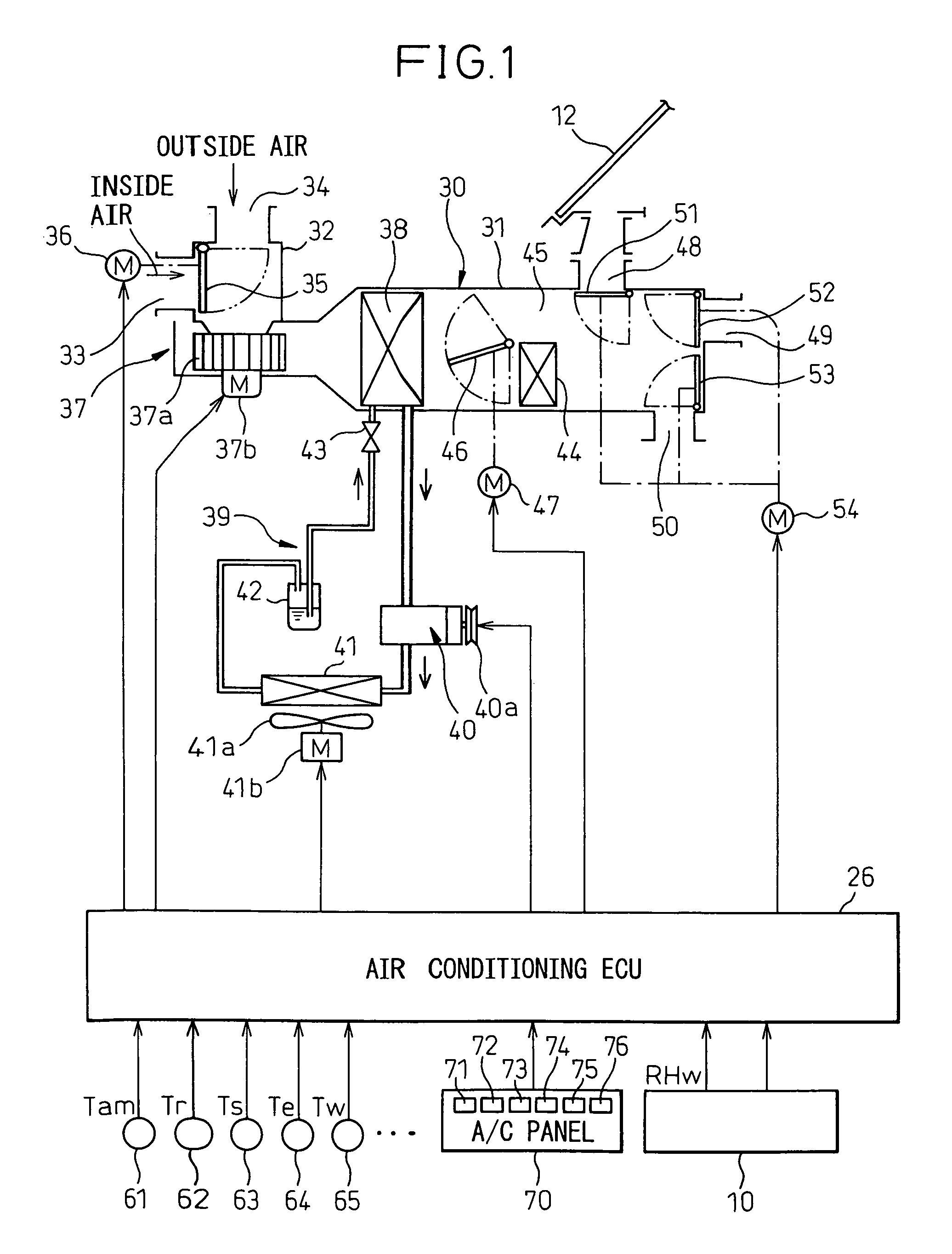
[0052]FIG. 1 shows the schematic configuration of a vehicle air-conditioner according to a first embodiment of the present invention.

[0053]The vehicle air-conditioner has an inside air-conditioning unit 30 arranged behind an instrument panel at the front most part of a passenger compartment. This inside air-conditioning unit 30 has a case 31. Inside the case 31, an air passage is formed for blowing air toward the inside of the vehicle compartment.

[0054]At the upstream most part of the air passage of the case 31, an inside / outside air switching box 32 is provided. An inside air introduction port 33 and an outside air introduction port 34 are able to be switched to open and close by an inside / outside air switching door 35. This inside / outside air switching door 35 is driven by a servo motor 36.

[0055]At the downstream side of the inside / outside air switching box 32, an electrically powered blower 37 is provided for blowing air toward the inside of the vehicle compartment. This blower 3...

second embodiment

[0162]When the engine water temperature is low at the initial start of a heating operation, the heater core 44 may not sufficiently warm the air-conditioning air, cool air may be blown out from the blowing ports 48 to 50, and the passengers may be discomforted as that cool air strikes them.

[0163]Therefore, as shown in FIG. 15, in the related art, when the engine water temperature is low, after the start of a heating operation, the air-conditioning use electrically driven blower 37 is stopped for a certain time until the engine water temperature reaches a certain temperature (33° C.) or more, then the air-conditioning use electrically powered blower 37 is started. By doing this, cool air is prevented from striking the passengers.

[0164]However, when the air-conditioning use electrically powered blower 37 is stopped, the respiration of the passengers causes the humidity in the vehicle compartment to rise and the window glass ends up fogging up. On the other hand, as shown in FIG. 16, i...

third embodiment

[0170]In the first embodiment, one of the control modes 10 to 60 was selected as the defrost control based on the window glass surface relative humidity RHW and the blowing mode was determined along with this selection, but at the initial start of the heating operation when the engine cooling water is low in temperature, cool air is blown out from the blowing ports. At this time, if cool air is directly blown from the face blowing port 49 and the foot blowing port 50 to the passengers, the passengers will sometimes be discomforted.

[0171]Therefore, in the third embodiment, as shown in FIG. 19, when the temperature of the engine cooling water is less than 33° C., the defrost mode is selected. After this, when the temperature of the engine cooling water rises and becomes higher than 38° C., one of the control modes 10 to 60 is selected as shown in FIG. 12 based on the window glass surface relative humidity RHW and the blowing mode is selected along with that selection. That is, the blo...


PUM

PropertyMeasurementUnit
dielectric constantaaaaaaaaaa
humidityaaaaaaaaaa
temperatureaaaaaaaaaa

Abstract

A vehicle air-conditioner provided with an inside air-conditioning unit introducing at least one of inside air and outside air, adjusting the state of the introduced air, and blowing it out into the vehicle compartment, where an air-conditioning electronic control device judges if window glass is liable to fog up based on a window glass surface relative humidity near the window glass in the compartment (degree of ease of fogging). When it is judged that the window glass is liable to fog up, the inside air-conditioning unit is controlled to prevent the window glass from fogging up in defrost control, while when it is judged that the window glass is resistant to fogging, the inside air-conditioning unit is controlled to introduce at least inside air into the compartment.

Description

BACKGROUND OF THE INVENTION[0001]1. Field of the Invention[0002]The present invention relates to a vehicle air-conditioner conditioning the air inside a vehicle compartment.[0003]2. Description of the Related Art[0004]In the past, in automatic air-conditioning control of a vehicular air-conditioner, the inside / outside air intake mode, blowing port mode, and blower level have been controlled based on a target blowing temperature TAO so as to maintain the vehicle compartment temperature at a set temperature (for example, see Japanese Patent Publication (A) No. 2000-142077).[0005]In this control, in air-conditioning in the winter, in particular at times of low outside air temperature, the outside air mode was used for the air-conditioning in order to prevent the front window glass from fogging up. Further, at the initial start of heating, the blowing port mode was set to the foot / defrost mode for a certain time in order to prevent the front window glass from fogging up.[0006]However, a...

Claims


Application Information

Patent Timeline
Patent Type & Authority Patents(United States)
IPC IPC(8): F25D21/00F25D17/04F25B49/00F24F11/00G05D21/00G05D22/02F24F6/00F24F3/14F25D21/06B01F3/02B01F23/10
CPCB60H1/00849B60H1/00785
Inventor HIRAI, SHINICHIROKATAOKA, TAKUYA
Owner DENSO CORP
Why Eureka
Try Eureka