Suspended cable support system

a technology of supporting system and cable, which is applied in the direction of mechanical equipment, show shelves, hangers, etc., can solve the problems of additional labor required to assemble the various components of the separate sections of the suspension system, the cost of erecting such a labor intensive system could prove to be cost prohibitive, and the inability to accommodate the vast amount of cable runs required

Active Publication Date: 2011-06-14
JETTE ROGER
View PDF92 Cites 17 Cited by
  • Summary
  • Abstract
  • Description
  • Claims
  • Application Information

AI Technical Summary

Problems solved by technology

Such installations were typically made in facilities which simply were not designed to accommodate the vast amount of cable runs required to operate the typical large computer system.
A common problem experienced in utilizing cable suspension systems is maintaining organization of the various cables, conduits, pipes, etc. which are routed above the floor, proximate the ceiling and the like.
One drawback of such a suspension systems is the additional labor required to assemble the various components of the separate sections making up the suspension system.
In geographic regions with particularly high labor rates, the cost of erecting such a labor intensive system could prove to be cost prohibitive.
An additional drawback of such systems is the high cost of storing and shipping the components of the system in that the components may not be readily stacked and / or nested in order to reduce storage space and the like.

Method used


Image

  • Suspended cable support system
  • Suspended cable support system
  • Suspended cable support system

Examples


Embodiment Construction

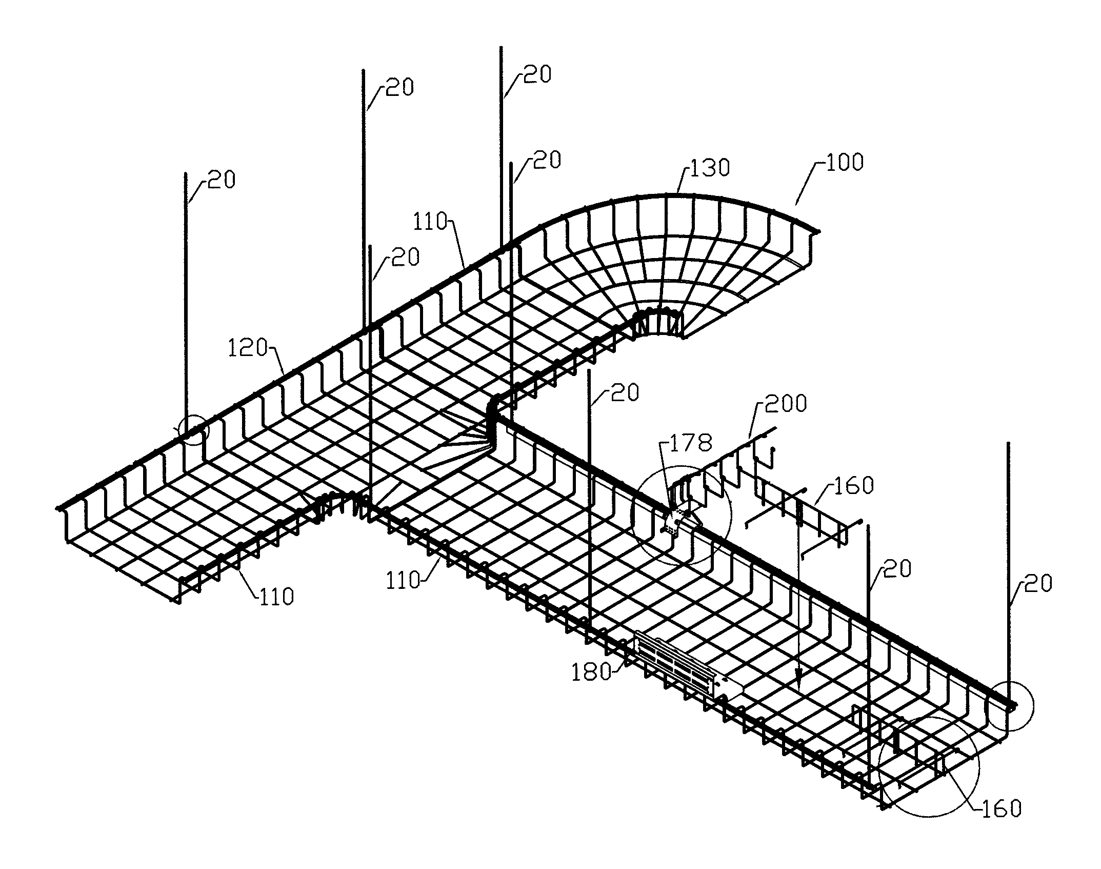
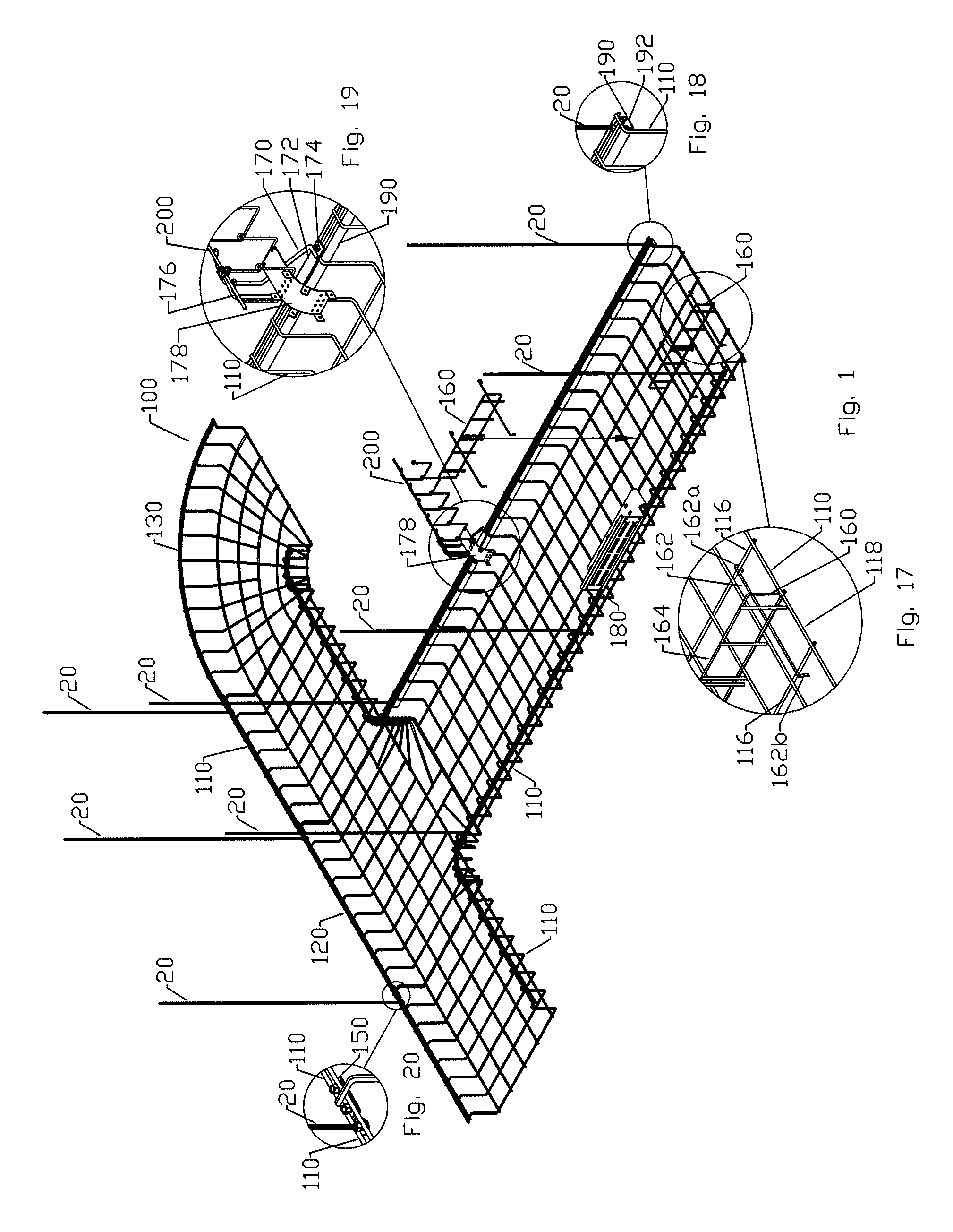
[0055]Referring now in specific detail to the drawings in which like reference numerals identify similar or identical elements throughout the several views, and initially to FIG. 1, one embodiment of a support system constructed in accordance with the present disclosure is shown generally as cable support system 100.

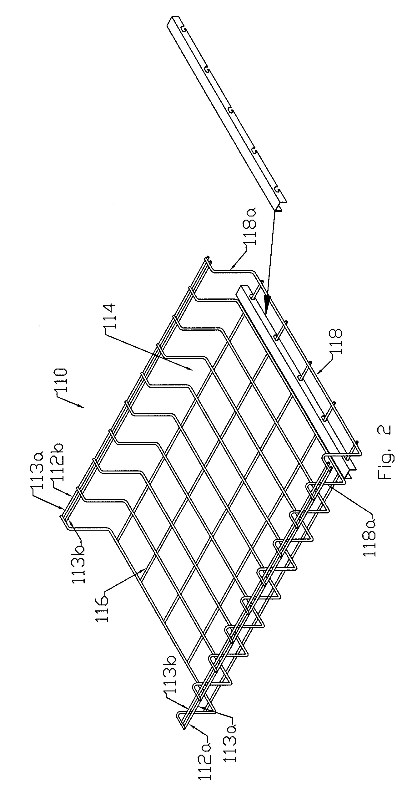
[0056]Generally, cable support system 100 includes a series of suspension rods or the like 20 depending from a ceiling, soffit, rafter or other suitable over-head structure (not shown). Cable support system 100 further includes any number of linear cable trays 110, T-shaped cable trays 120 and / or arcuate cable trays 130. It is contemplated and understood that the number of cable trays 110, 120 and 130 may vary from installation to installation depending on the need and configuration of the supporting structure.

[0057]As seen in FIG. 1, various cable trays 110, 120, 130 may be joined to one another by a coupling element 150 (see FIG. 13) including a plate 152 which extends...


PUM


Abstract

According to an aspect of the present disclosure, a suspended cable support system is provided. The suspended cable support system includes a plurality of suspension rods; and at least one cable tray. Each cable tray includes a pair of stringer elements, wherein each stringer element is configured for connection to at least one suspension rod; and a channel section depending from the pair of stringer elements. The channel section defines a passageway for supporting runs of cable thereon. The channel section includes a plurality of riser portions connected to the pair of stringer elements.

Description

CROSS-REFERENCE TO RELATED APPLICATION[0001]The present application claims the benefit of and priority to U.S. Provisional Application Ser. No. 60 / 844,480, filed on Sep. 14, 2006, the entire content of which is incorporated herein by reference.BACKGROUND[0002]1. Technical Field[0003]The present disclosure relates to suspended support systems and, more particularly, to a cable support system capable of being suspended.[0004]2. Description of Related Art[0005]Cable suspension systems have been developed to provide the additional utility space needed in various different conduit or cable intensive environments where the original construction did not provide adequate means of accommodating the vast amount of conduit or cable. For example, probably the most common environment requiring vast amounts of additional protected space is for large computing systems. Such installations were typically made in facilities which simply were not designed to accommodate the vast amount of cable runs r...

Claims


Application Information

Patent Timeline
Patent Type & Authority Patents(United States)
IPC IPC(8): A47F5/08
CPCF16L3/26H02G3/32H02G3/0443
Inventor JETTE, ROGER
Owner JETTE ROGER
Why Eureka
Try Eureka