Bayonet-coupled draft shield arrangement for balance

a shield arrangement and bayonet technology, applied in the direction of weighing apparatus details, instruments, measurement devices, etc., can solve the problems of difficult cleaning and removal, increased and less user-friendly balance, etc., to achieve convenient cleaning, easy disconnection, and overall height of the balance

Active Publication Date: 2011-06-14
METTLER TOLEDO GMBH
View PDF14 Cites 13 Cited by
  • Summary
  • Abstract
  • Description
  • Claims
  • Application Information

AI Technical Summary

Benefits of technology

[0007]The concept disclosed has the advantage that the floor for the draft shield arrangement can take the form of a simple plate which only carries the second part of the fastening arrangement, but that there are no other components such as guiding constraints. The connection of the second part of the fastening arrangement to the floor can be accomplished in a simple manner, so that the height of the floor, and thus the overall height of the balance, can be kept low, while the cleaning can be performed easily.
[0008]A substantial improvement in the sense of the objective stated above is further achieved through a design where the second part of the fastening arrangement is attached to the floor of the draft shield arrangement in such a way that it can easily be disconnected. This means that the connection can be released without any tool and with a simple manipulation. In this way the cleaning can be performed with the greatest of ease by disconnecting the second part of the fastening arrangement, because all that remains to be cleaned in this case is the floor plate with its opening. There are no additional components left to deal with, and in particular none with a complicated configuration. The removed second part of the fastening arrangement can be designed as a part of simple configuration which can be put through a separate cleaning procedure, which will in this case likewise be easy to perform.
[0009]The attachment of the second part of the fastening arrangement to the floor of the draft shield arrangement can be accomplished in different ways. It is possible that the parts involved are designed so that the second part of the fastening arrangement can be snapped or screwed to the floor. However, it is particularly advantageous if the second part of the fastening arrangement is given a ring-shaped configuration and cooperates with the opening of the floor in the manner of a bayonet coupling. This makes the part particularly easy to disconnect and reconnect, which greatly facilitates cleaning.
[0011]According to a further developed version, the second part of the fastening arrangement has a channel on the topside to catch and drain liquids. This measure serves to prevent that spilled liquids could get into the interior of the balance and cause malfunctions.
[0014]The fact that the draft shield arrangement is connected centrally at the passage for the load-introducing member also makes it possible for the floor of the draft shield arrangement to function as a shock absorber, if the floor is made of a material with resilient and attenuating properties. Thus, impact forces that may hit the draft shield arrangement are damped along their propagation into the balance. This has the advantage that oscillations caused by this kind of an impact will decay faster, whereby the waiting time until a weighing process can take place is shortened, so that lost time is avoided.

Problems solved by technology

A sliding latch of this kind has the disadvantage that it involves a complicated mechanism which has to be accommodated in the floor plate of the draft shield arrangement.
This mechanism, in particular the guiding constraint for the sliding latch, is difficult to clean and has to be taken apart for a thorough cleaning.
Furthermore, due to the thickness of the floor of the draft shield arrangement, the overall height of the balance is increased, which makes the balance less user-friendly and affects the operating ergonomics of the balance unfavorably in particular with regard to the access to the weighing pan.
Thus, impact forces that may hit the draft shield arrangement are damped along their propagation into the balance.

Method used


Image

  • Bayonet-coupled draft shield arrangement for balance
  • Bayonet-coupled draft shield arrangement for balance
  • Bayonet-coupled draft shield arrangement for balance

Examples


Embodiment Construction

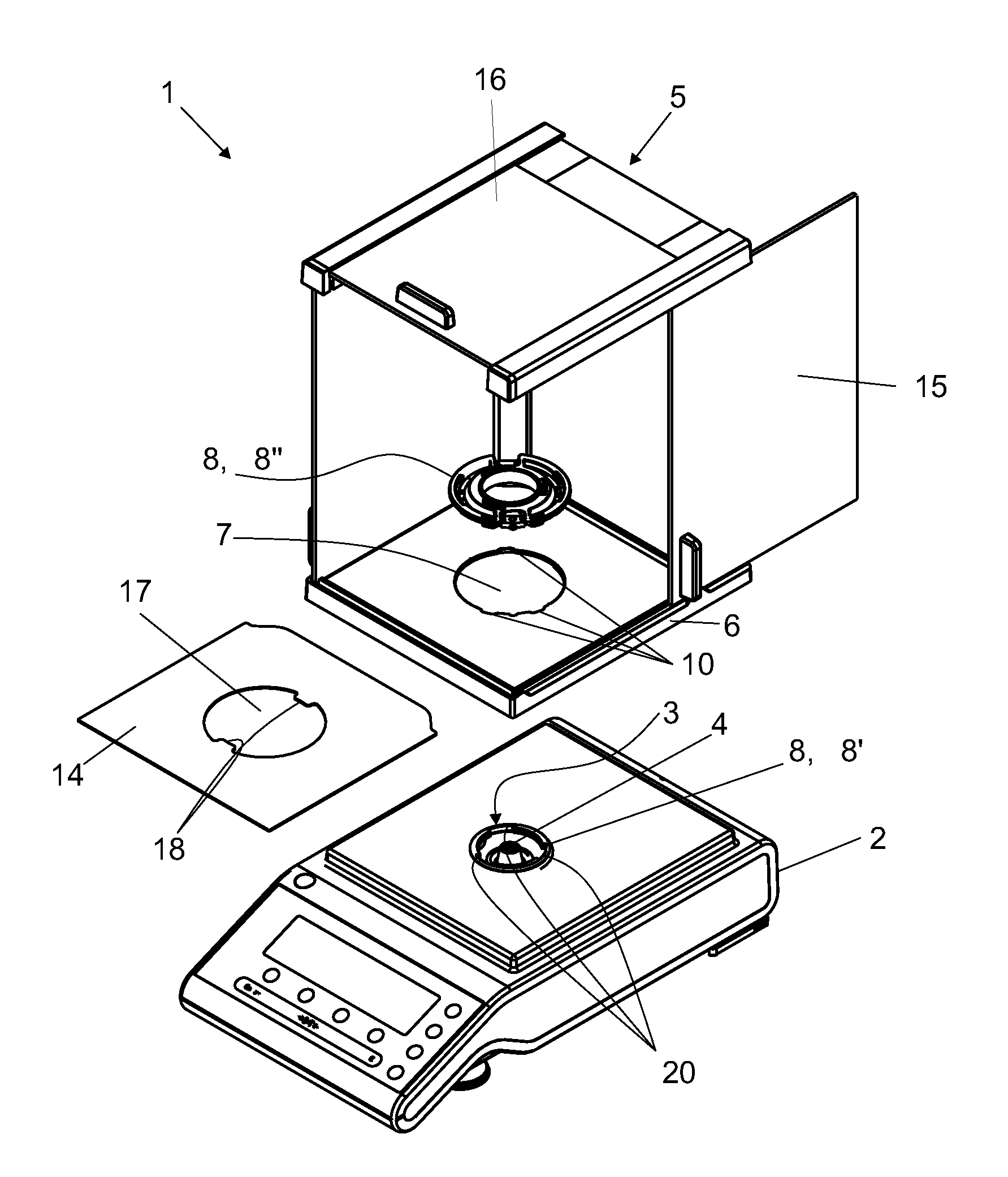
[0022]FIG. 1 illustrates a balance 1 with a balance housing 2 and a draft shield arrangement 5. The draft shield arrangement 5 has been taken off the balance housing 2, whereby the first part 8′ of the fastening arrangement 8 on the balance housing 2 has become visible. This first part 8′ of the fastening arrangement 8 is arranged at the rim of the opening 3, the latter serving as passage for the load-introducing member 4. A receiving element for the weighing object, for example a weighing pan, is set on the load-introducing member 4.

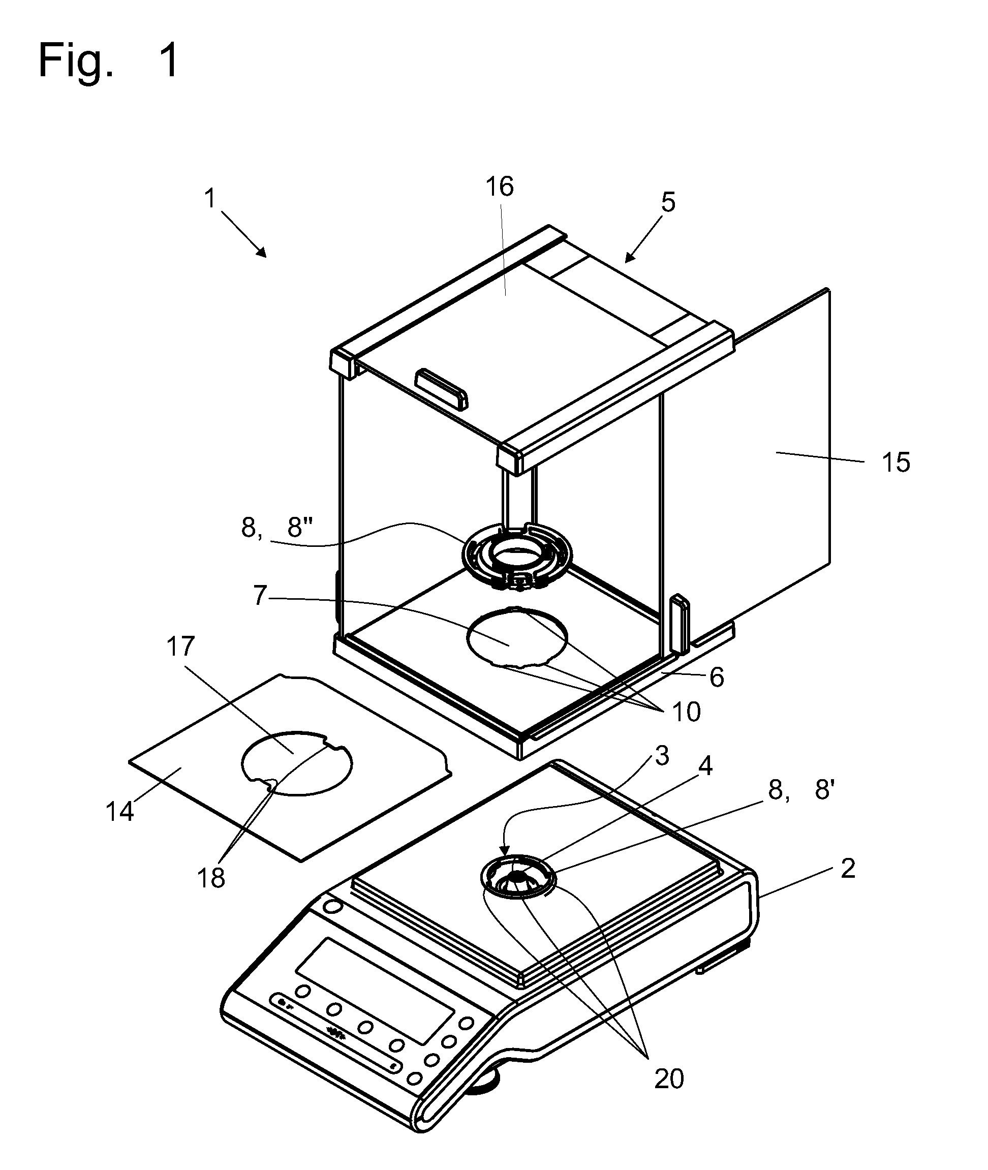
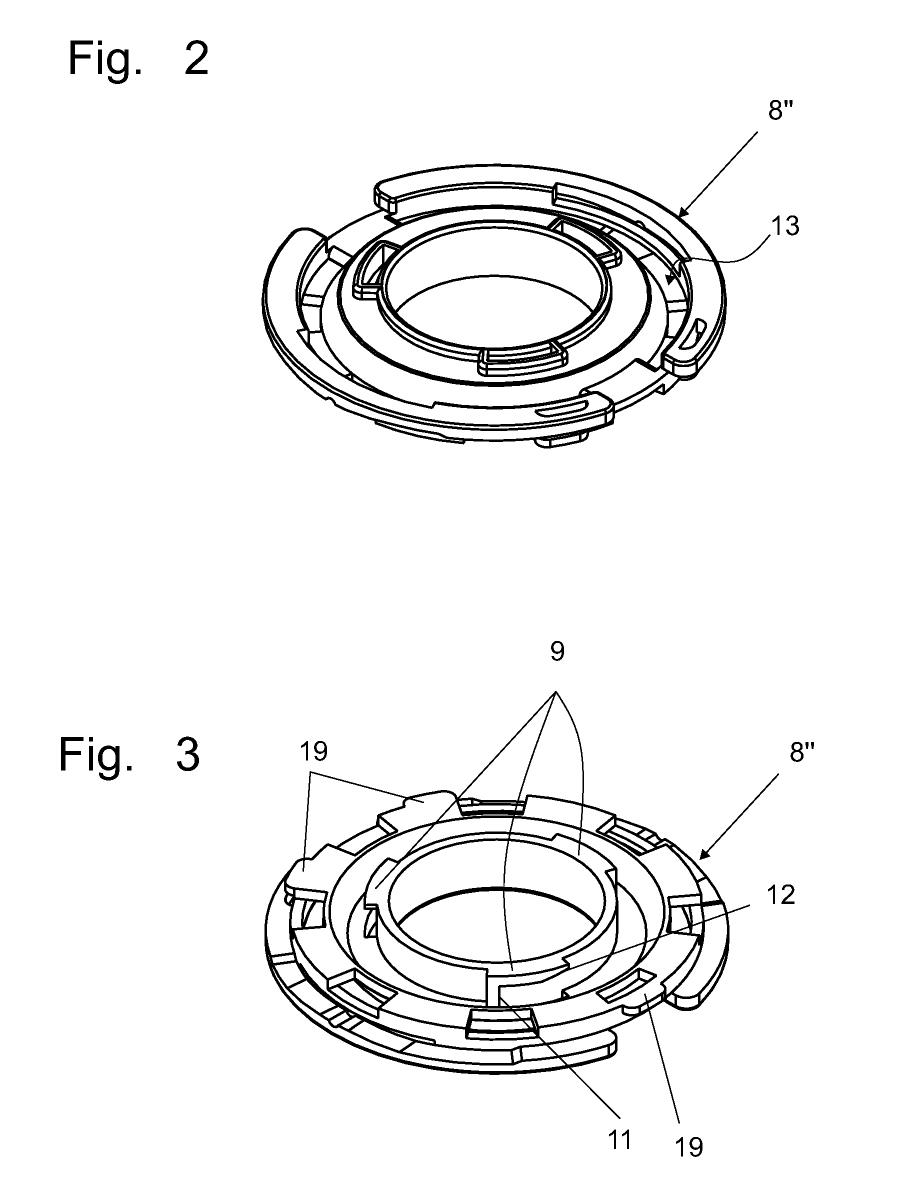
[0023]In order to prevent air drafts from affecting the precision of the weighing process, the draft shield arrangement 5 is set on top of the balance housing 2. This purpose is served by a second part 8″ of the fastening arrangement 8. The second part 8″ can cooperate with the first part 8′ of the fastening arrangement in the sense of a bayonet coupling as outlined in the drawing. Bayonet couplings of different configurations can be used here, as will ...


PUM


Abstract

A balance (1) has a balance housing (2), which, when the balance is set up for operation, has an opening at its topside to pass a load-introducing member (4). The housing has a draft shield arrangement (5), separable from, and attachable to, the housing. An opening (7) on a floor (6) of the draft shield arrangement corresponds to the housing opening and allows the load-introducing member to pass. A design that facilitates cleaning while keeping the height of the balance low is achieved with a fastening arrangement (8) for the draft shield arrangement. The fastening arrangement allows the draft shield arrangement to be fastened centrally at the load-introducing member passage. A rim on the housing opening operates as a first part (8′) and provides a form-locking connection with a second part that is attached to the draft shield arrangement at the draft shield floor opening.

Description

CROSS-REFERENCE TO RELATED APPLICATIONS[0001]This application is entitled to, and claims, a benefit of a right of priority under 35 USC §119 from European patent application 08 15 1093.5, filed on 6 Feb. 2008, the content of which is incorporated by reference as if fully recited herein.TECHNICAL FIELD[0002]The invention concerns a balance with a balance housing to accommodate the functional elements of the balance wherein, for a balance that is set up for operation, the balance housing has at its topside an opening for the passage of the load-introducing member and is equipped with a draft shield arrangement which in its entirety can be separated from and attached to the balance housing, and wherein the floor of the draft shield arrangement also has an opening that matches the opening of the balance housing for the passage of the load-introducing member.BACKGROUND OF THE ART[0003]Draft shield arrangements have the purpose to ensure that air drafts do not compromise the weighing resu...

Claims


Application Information

Patent Timeline
Patent Type & Authority Patents(United States)
IPC IPC(8): G01G21/28
CPCG01G21/286
Inventor MOCK, DANIEL
Owner METTLER TOLEDO GMBH
Why Eureka
Try Eureka