Microphone with irregular diaphragm

a technology of irregular diaphragm and microphone, which is applied in the field of microphones, can solve problems such as degrading signal quality, and achieve the effect of improving the signal-to-noise ratio

Active Publication Date: 2011-06-14
INVENSENSE
View PDF73 Cites 27 Cited by
  • Summary
  • Abstract
  • Description
  • Claims
  • Application Information

AI Technical Summary

Problems solved by technology

When too close, however, the diaphragm and plate may contact during use and thus, possibly stick together.
Even if they do not stick together, contact between the diaphragm and backplate can degrade signal quality.

Method used


Image

  • Microphone with irregular diaphragm
  • Microphone with irregular diaphragm
  • Microphone with irregular diaphragm

Examples


Embodiment Construction

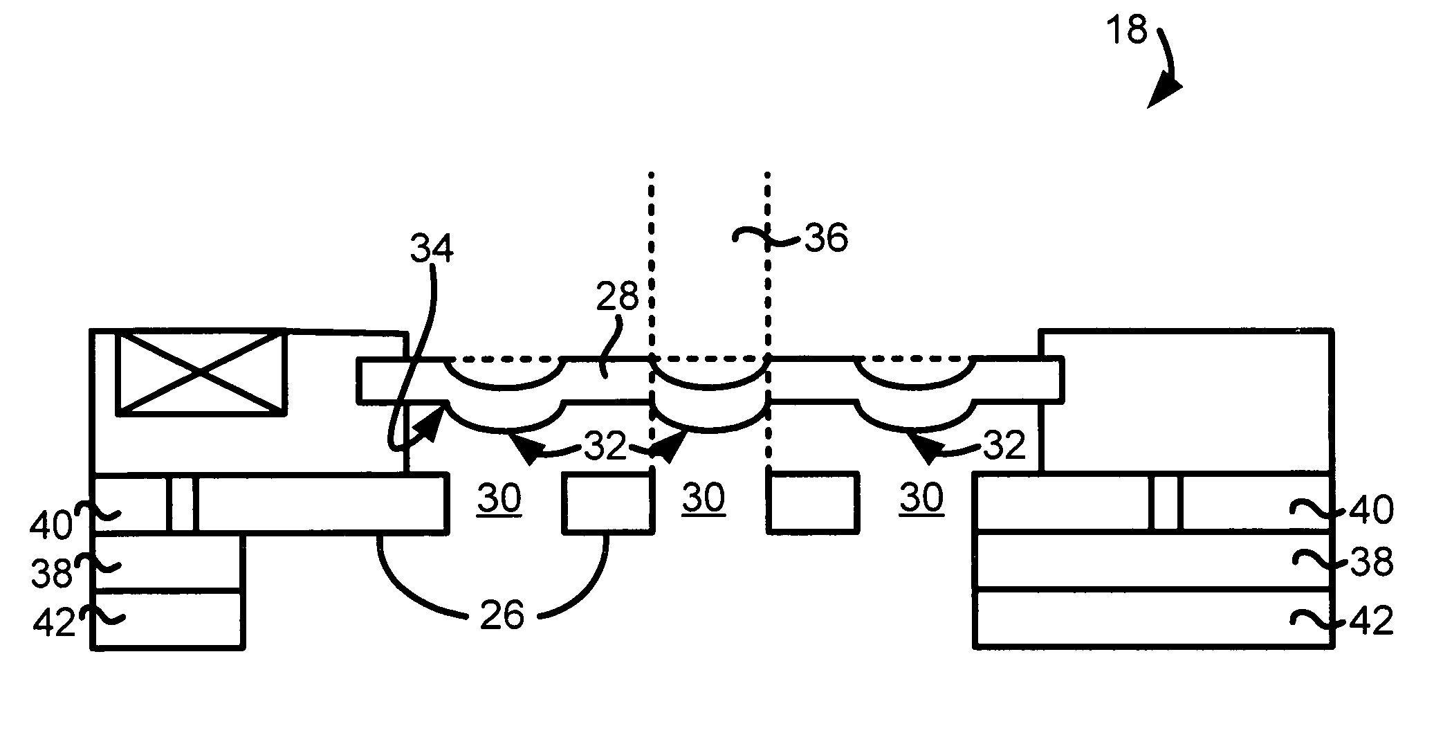
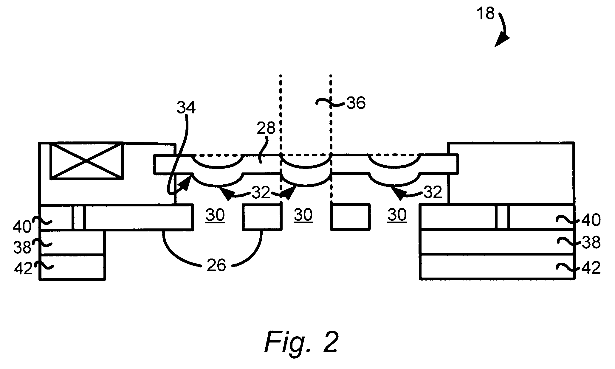
[0019]In illustrative embodiments, a MEMS microphone has a diaphragm that is contoured to improve its signal to noise ratio. To that end, the diaphragm has one or more protrusions that each are substantially aligned with at least one of the holes through its backplate. By doing this, portions of the diaphragm are closer to the backplate, thus increasing capacitance. Moreover, placing the protrusions in this manner relative to the holes should mitigate stiction problems if there is contact with the backplate. Details of illustrative embodiments are discussed below.

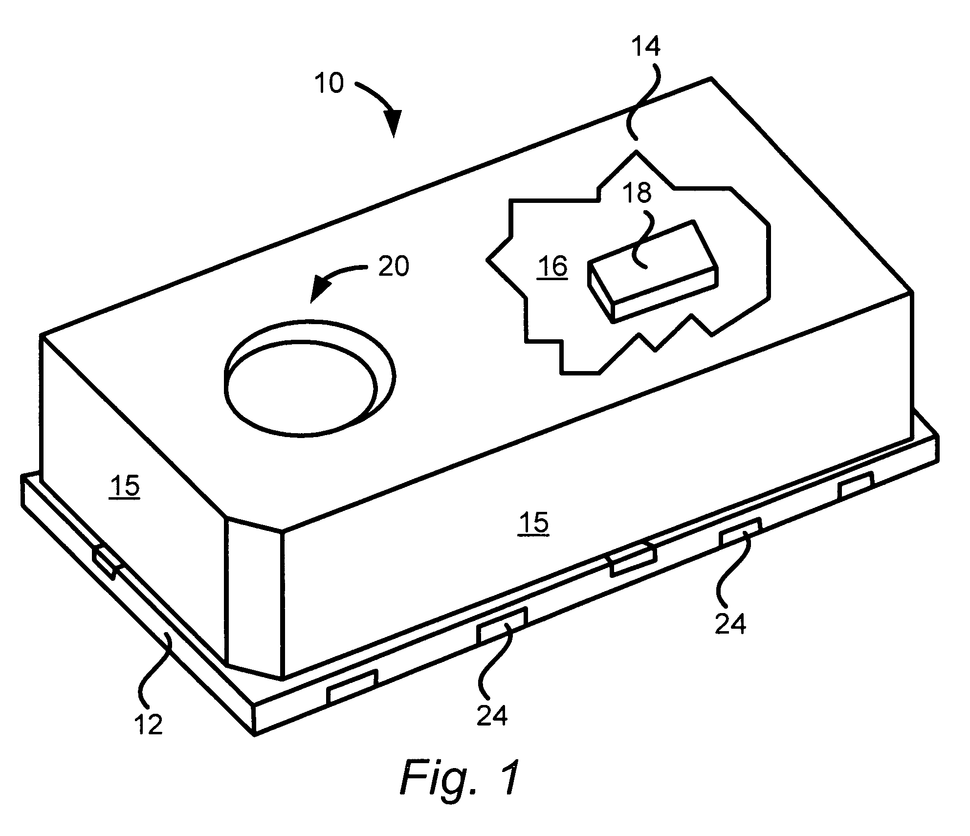
[0020]FIG. 1 schematically shows a top, perspective view of a packaged microphone 10 that may be configured in accordance with illustrative embodiments of the invention. Among other things, the microphone 10 has a package base 12 that, together with a corresponding lid 14, forms an interior chamber 16 containing a microphone chip 18 (discussed below, also see FIG. 2) and, if desired, microphone circuitry (not shown). The li...


PUM

PropertyMeasurementUnit
thickaaaaaaaaaa
thickaaaaaaaaaa
thickaaaaaaaaaa

Abstract

A microphone is formed to have a diaphragm that is configured to improve signal to noise ratio. To that end, the microphone has a backplate having a hole therethrough, and a diaphragm movably coupled with the backplate. The diaphragm has a bottom surface (facing the backplate) with a convex portion aligned with the hole in the backplate.

Description

PRIORITY[0001]This patent application claims priority from provisional U.S. patent application Ser. No. 60 / 710,517, filed Aug. 23, 2005, entitled, “MICROPHONE WITH IRREGULAR DIAPHRAGM,” and naming Jason Weigold of Somerville, Mass. as inventor, the disclosure of which is incorporated herein, in its entirety, by reference.FIELD OF THE INVENTION[0002]The invention generally relates to microphones and, more particularly, the invention relates to improving the performance of microphones.BACKGROUND OF THE INVENTION[0003]Condenser MEMS microphones typically have a diaphragm that forms a capacitor with an underlying backplate. Among other things, the sensitivity of the microphone is a function of this capacitance. To increase sensitivity, microphone designers typically attempt to form the diaphragm as close to the backplate as possible when in a static state. When too close, however, the diaphragm and plate may contact during use and thus, possibly stick together. Even if they do not stick...

Claims


Application Information

Patent Timeline
Patent Type & Authority Patents(United States)
IPC IPC(8): H04R25/00
CPCG01L9/0042H04R7/14H04R19/005H04R19/04H04R31/00H04R31/003Y10T29/49005H04R2499/11Y10T29/43H04R27/00
Inventor WEIGOLD, JASON W.
Owner INVENSENSE
Why Eureka
Try Eureka