Slitter tool for cutting a tubular sheath of a guide catheter

a catheter and tube tube technology, applied in the field of intracorporal lead implantation, can solve the problems of difficult extraction procedure, difficult intervention, and difficulty in latter type of lead

Active Publication Date: 2011-06-21
SORIN CRM
View PDF17 Cites 55 Cited by
  • Summary
  • Abstract
  • Description
  • Claims
  • Application Information

AI Technical Summary

Benefits of technology

It is an object of the present invention to palliate all these difficulties, by proposing a cutting tool of the slitter type which, from an ergonomic point of view, is better than what has been proposed up to know, and allows a simple and safe handling by the surgeon.
In one embodiment, the cutting area has, level with the rear of the blade, reliefs for separating the lips of the cut guide-catheter, said separator reliefs being placed at both sides, and at the rear of said tubular guide. More preferably, the separator reliefs are each have respective grooves for guiding the lips of the cut guide-catheter, said leads being oriented generally parallel to the cutting direction (X). The guiding grooves are optionally placed at the front of the holding pathway, to provide a smooth guiding action of the cut guide-sheath away, and the guiding grooves also may extend into the holding pathway.

Problems solved by technology

The insertion of the latter type of leads, carried out through endocavitary approaches, is a particularly tricky intervention, taking into account the difficult access to the coronary sinus entrance via the right atrium, and also the required accuracy for the pacing sites once the lead is guided to its desired position and immobilized within the coronary network.
Once the lead is in place, the guide-catheter needs to be extracted, and the extraction procedure is tricky because the lead must not be displaced, or its position or orientation altered as a result of the extraction.
One other difficulty of this extraction step is due to the presence of the electrical connector, at the proximal end of the lead.
However, cutting of such a sheath along its whole length leads to a weakness and a lower rigidity of the guide-catheter, with a risk of folding and lower transmission of efforts (applied forces) during its setting up preparatory to an intervention event.
This method however leads to an increasing number of steps required for setting up and assembling the different elements, and also renders the intervention procedure more complicated.
One of the main difficulties inherent to this method, lies in the risk of a lead displacement during the catheter extraction.
This implies a significantly longer intervention time, particularly with left ventricular leads, which take a very long time to implant anyway, and additional risks associated with the prolongation of an already very long intervention.
In particular, the risk referred to above, which is a large risk, of a lead displacement during the cutting operation, is increased by the fact that the lead is not maintained in the critical area of cutting of the catheter, an area where the constraint during the operation, is focused.
For that reason, there is a remaining risk of a displacement of the lead relative to the catheter, with the formation of a “loop” level with the maintaining area, leading to a high risk of displacement of the opposite end (distal end) located level with the implantation site, such a displacement requiring a complete starting over of the procedure.
Also, with the slitting tools that have been proposed so far, the prehension of the tool is ensured by a pinching between the thumb and forefinger, with a risk of instability during handling that is as much high as the required cutting force is high, notably in the case of relatively thick and strongly reinforced guide-catheters.
As for the prehension of the lead, it is equally ensured by the fingers, but at a relatively large distance from the area where the cutting of the guide-catheter is effectively realized, which reduces the stability of the whole assembly set up during the operation.

Method used


Image

  • Slitter tool for cutting a tubular sheath of a guide catheter
  • Slitter tool for cutting a tubular sheath of a guide catheter
  • Slitter tool for cutting a tubular sheath of a guide catheter

Examples


Embodiment Construction

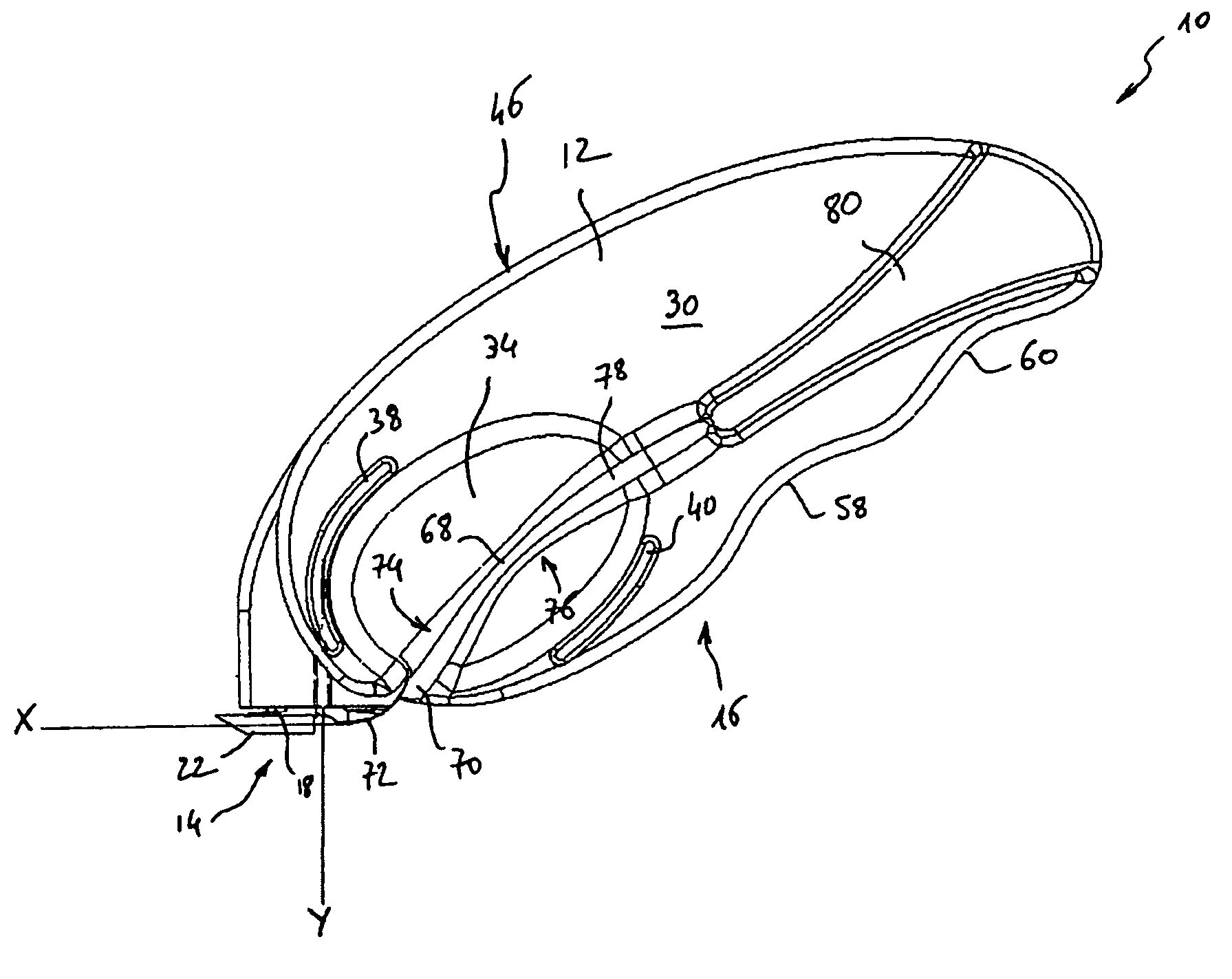
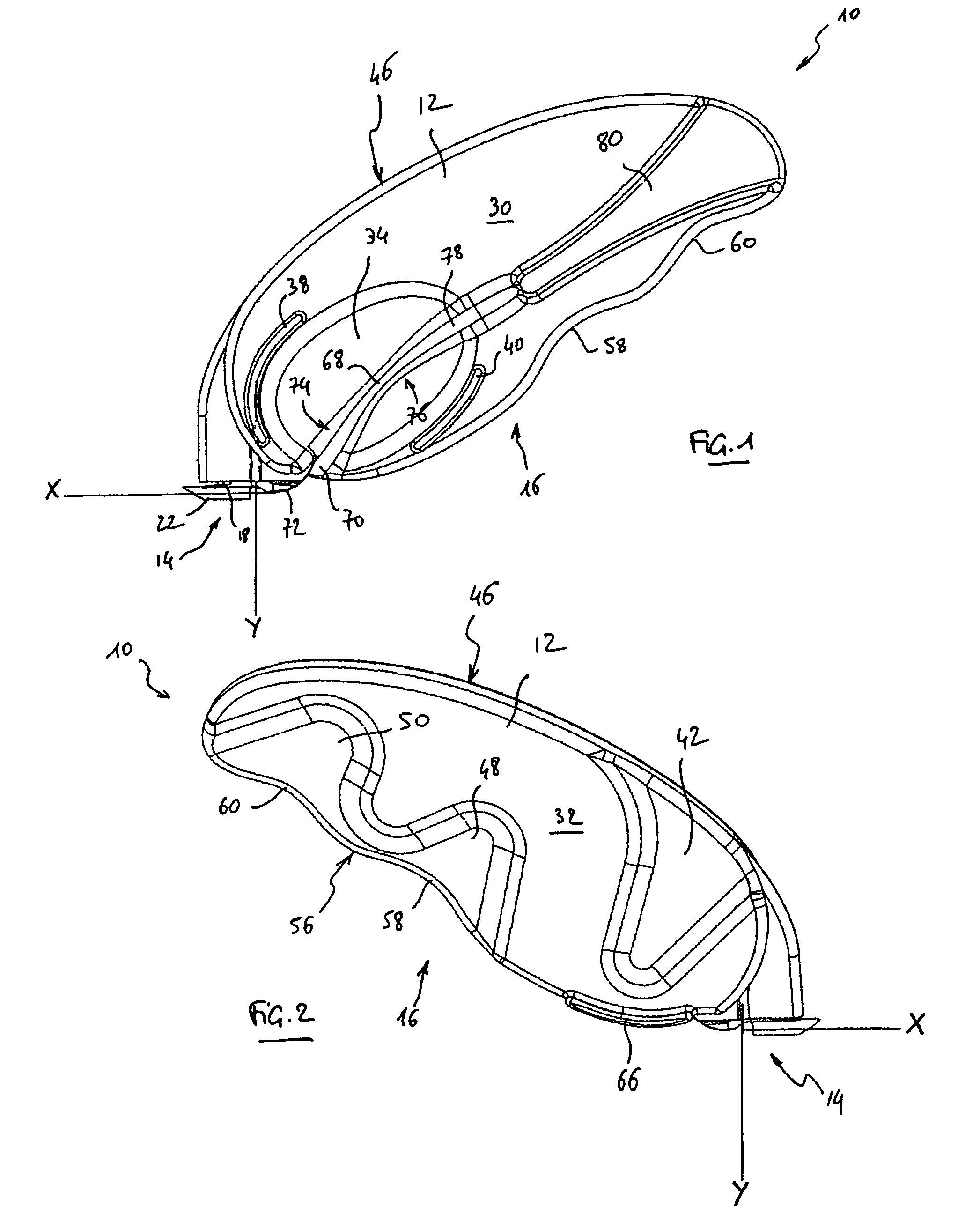
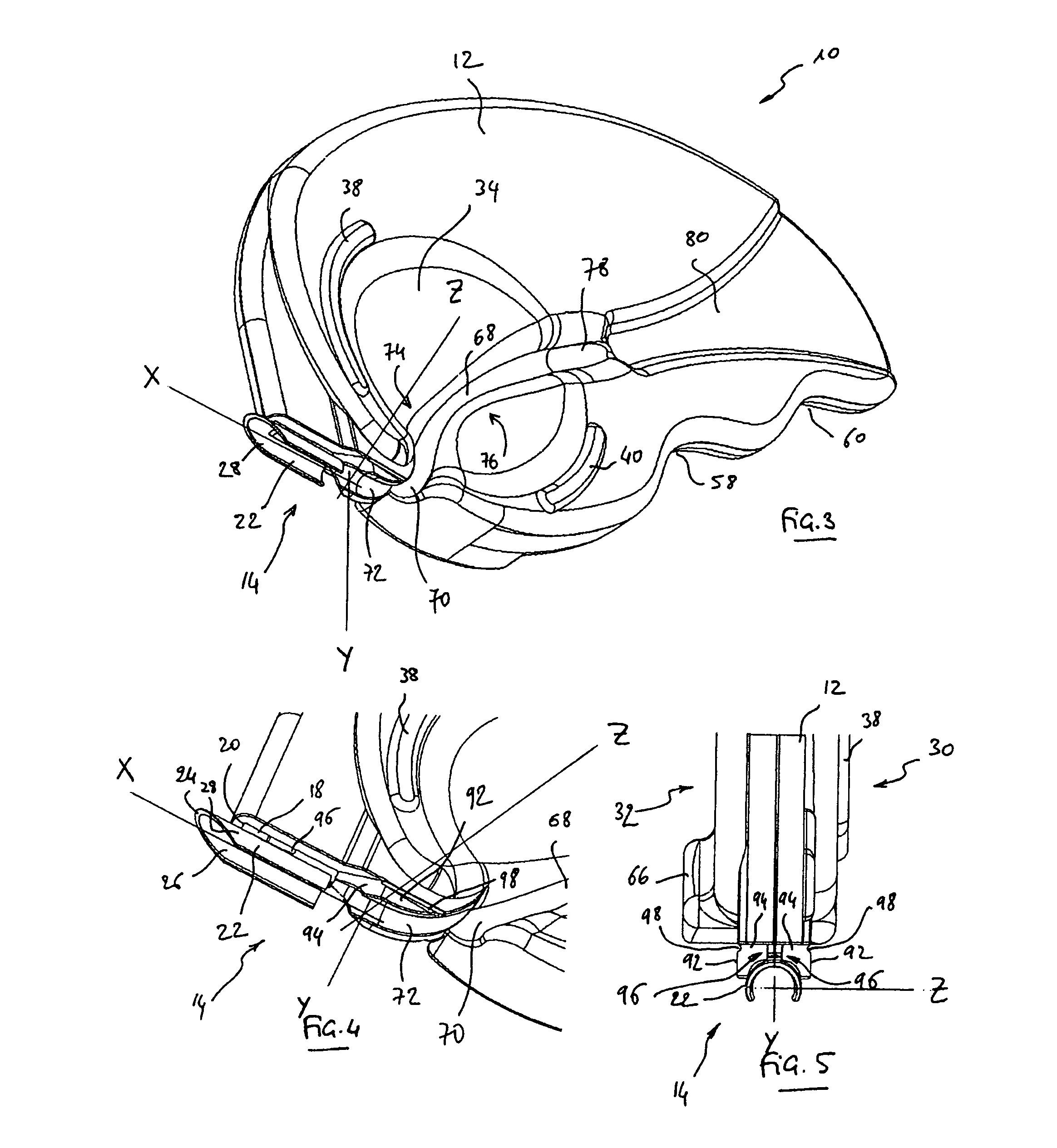
One will now describe an embodiment of the slitter tool according to a preferred embodiment of the present invention. With reference to the figures, reference 10 generally corresponds to the slitting tool or “slitter” tool of the present invention. Tool 10 comprises a blade holder body 12 with a roughly flattened shape, comprising a cutting area 14 and a prehension area 16.

Tool 10, for example, presents the following typical overall dimensions: length (the longer longitudinal dimension of the tool) of 65 to 100 mm, width (the longer transversal dimension) of 35 to 40 mm, and thickness of 5 to 6 mm. Of course, these dimensions are exemplary, and in no way limitative; and one of ordinary skill in the art will understand that the size of tool 10 must be such that the tool may be handled in the inside of a surgeon's hand, and not merely between the thumb and the forefinger, as it is the case with the various slitter tools that have been proposed by the prior art so far.

Cutting area 14 c...


PUM

PropertyMeasurementUnit
distanceaaaaaaaaaa
distanceaaaaaaaaaa
distanceaaaaaaaaaa

Abstract

A tool for cutting or slitting the tubular sheath of a guide-catheter in the presence of a lead placed in this sheath. The tool (10) has a flattened, substantially planar blade holder body (12) with a cutting area (14) and a prehension area (16). The cutting area has a blade (18) and a tubular guide (22) receiving the lead for isolating it from the guide-catheter. The prehension area (16) has on a first side (30) an area for receiving the thumb and a lead holding pathway (68) spreading in the continuation of the tubular guide following an overall orientation forming an angle with this guide. The thumb reception area has a concave footprint (34) crossed through and through by the lead holding pathway (68), which spreads in the prehension area following an “S” shaped curve having a first curved area (74) and a second counter-curved area (76). The minimal distance between the blade (18) and the contour of the first footprint (34) is to the most equal to 15-20 mm.

Description

FIELD OF THE INVENTIONThe present invention is related to the implantation of intracorporal leads, more particularly leads for cardiac sensing / pacing that are usually associated with “active implantable medical devices” as such devices are defined by the Jun. 20, 1990 directive of the Counsel of European communities, and more specifically to implantable devices for cardiac pacing, resynchronization, cardioversion and / or defibrillation.BACKGROUND OF THE INVENTIONCardiac leads may be endocardial leads, such as leads for sensing / pacing in right heart cavities, or leads introduced in the coronary network, notably leads comprising an electrode positioned in front of a left cavity of the myocardium.The insertion of the latter type of leads, carried out through endocavitary approaches, is a particularly tricky intervention, taking into account the difficult access to the coronary sinus entrance via the right atrium, and also the required accuracy for the pacing sites once the lead is guide...

Claims


Application Information

Patent Timeline
Patent Type & Authority Patents(United States)
IPC IPC(8): A61B17/32A61M25/00
CPCA61M25/06A61M25/0668A61M2025/0675
Inventor SHAN, NICOLASOLLIVIER, JEAN-FRANCOIS
Owner SORIN CRM
Why Eureka
Try Eureka