Projection display device

a projection display and display device technology, applied in the field of projection display devices, can solve the problems of color non-uniformity in the displayed image, trapezoidal distortion in the projected image, and the inability to suppress the light amount, so as to suppress the trapezoidal distortion, shorten the throw distance, and significantly reduce the light amount of a specific color

Active Publication Date: 2011-06-21
SANYO ELECTRIC CO LTD
View PDF25 Cites 2 Cited by
  • Summary
  • Abstract
  • Description
  • Claims
  • Application Information

AI Technical Summary

Benefits of technology

[0016]The inventors of the present application have investigated, in developing a projection display device of oblique projection type, an approach of shortening a throw distance, while suppressing a trapezoidal distortion resulting from shifting an imager. As a result of the investigation, the inventors have confirmed a phenomenon that the light amount of a specific color is significantly lowered depending on shift of the imager, as a projection beam is moved from one end of a projection area toward the other end of the projection area, and that a displayed image has color non-uniformity resulting from lowering of the light amount of a specific color. The inventors have also confirmed that lowering of the light amount and color non-uniformity are remarkable, as the shift amount of the imager with respect to the optical axis of the projection optical system is increased.
[0017]The inventors of the present application have intensively investigated to overcome the aforementioned drawbacks while securing a shortened throw distance. As a result of analysis / investigation of the aforementioned drawbacks, the inventors have found a possibility that there may be a relation between lowering of the light amount of a specific color and color non-uniformity, and a polarization state of the light beam of the specific color. Based on the finding, the inventors have analyzed / investigated the relation between the polarization direction and the lowering of the light amount, and concluded that the lowering of the light amount and color non-uniformity can be eliminated by approximating the polarization direction of the light beam to the direction of shifting the imager with respect to the optical axis of the projection optical system.

Problems solved by technology

In the aforementioned arrangements, a trapezoidal distortion may occur in a projected image, resulting from oblique projection.
As a result, color non-uniformity may occur in a displayed image.
The above arrangement, however, fails to suppress lowering the light amount of a specific color, resulting from shifting the imager with respect to the optical axis of the projection optical system, and generation of color non-uniformity resulting from lowering the light amount of a specific color.

Method used


Image

  • Projection display device
  • Projection display device
  • Projection display device

Examples


Embodiment Construction

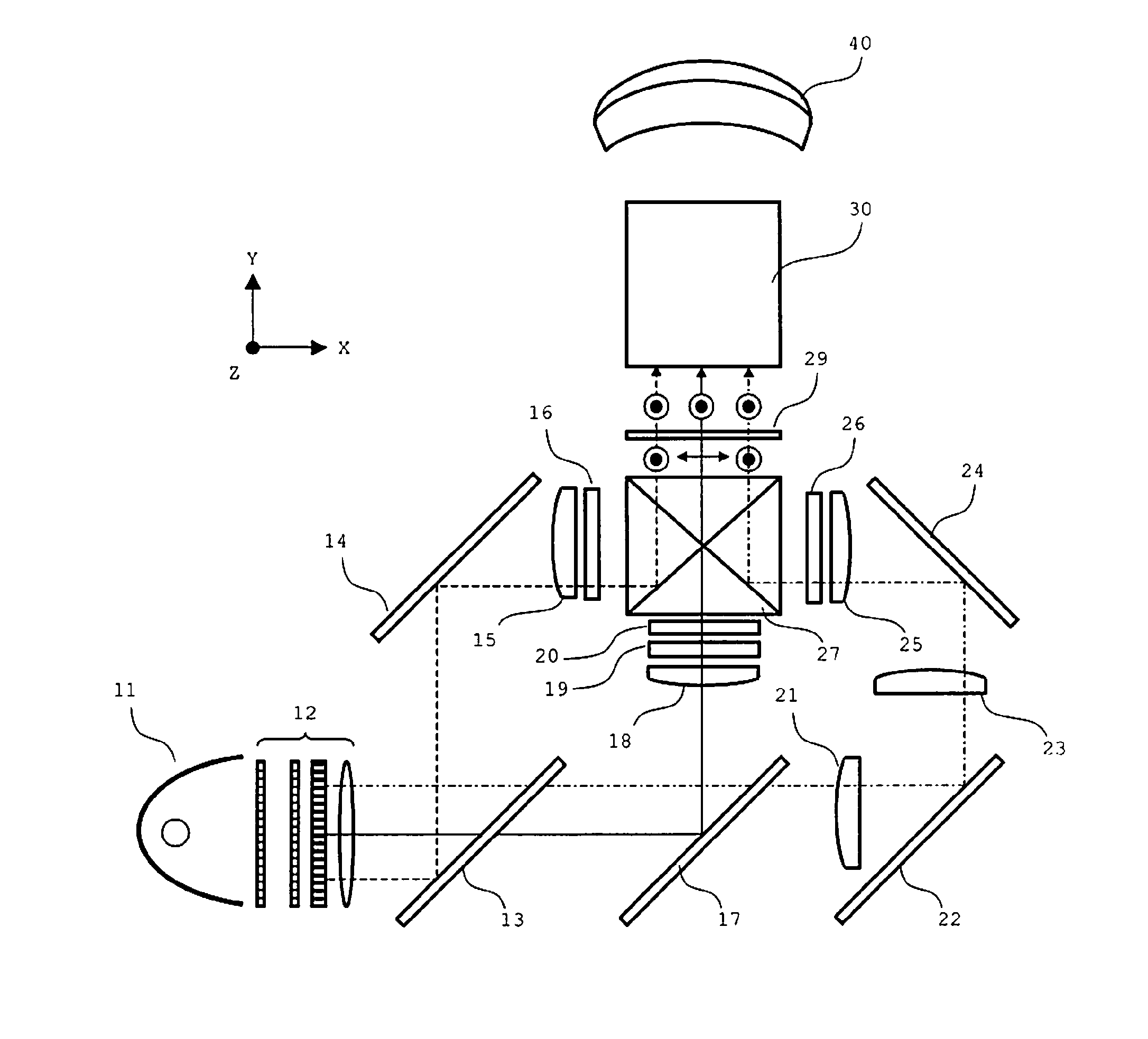
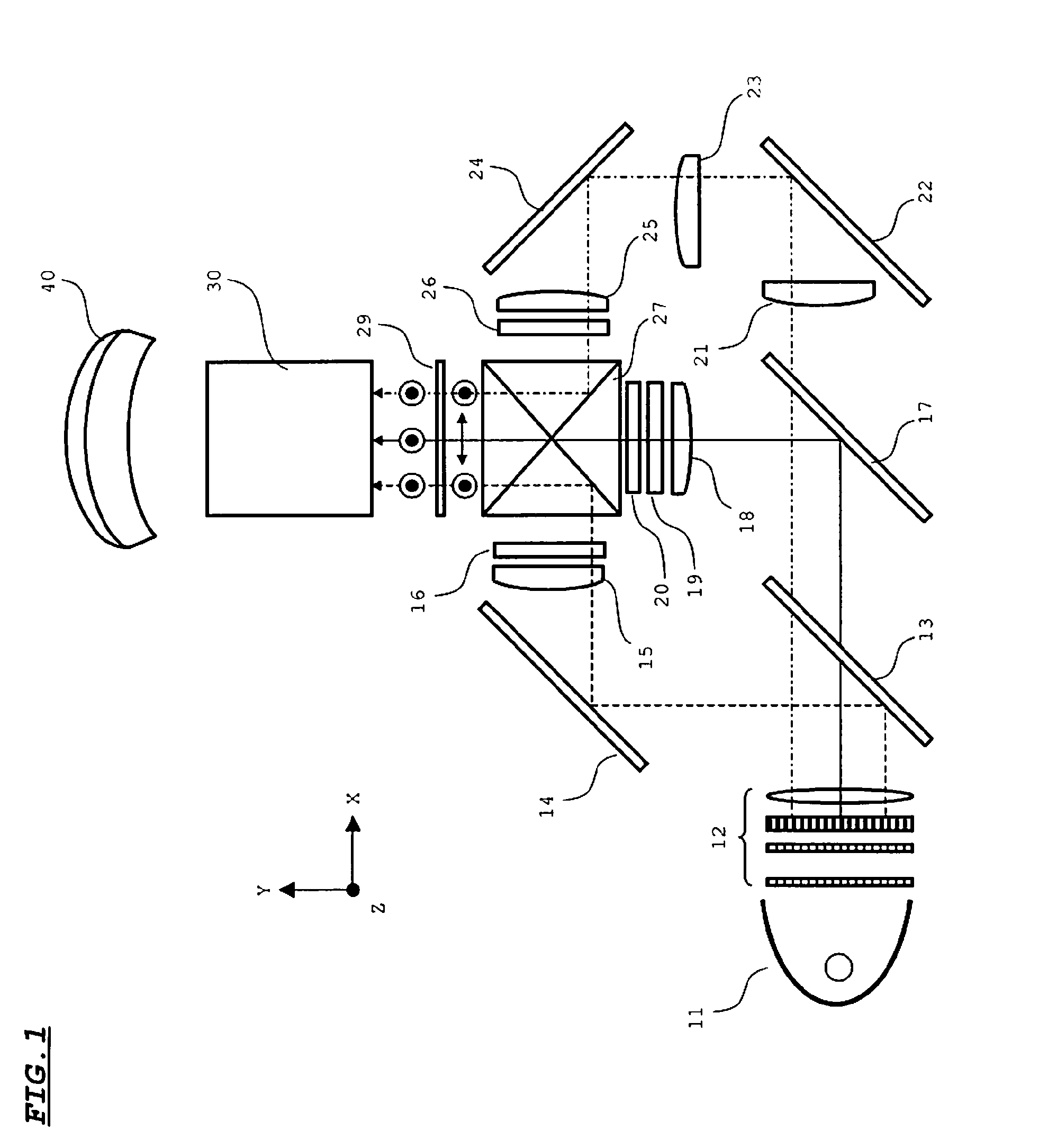
[0037]In the following, an embodiment of the invention is described referring to the drawings. FIG. 1 shows an optical system of a projector embodying the invention.

[0038]Referring to FIG. 1, a light source 11 includes a lamp and a reflector, and emits approximately parallel beams to an illumination optical system 12. The illumination optical system 12 includes a fly-eye integrator, a PBS (polarized beam splitter) array, and a condenser lens. The illumination optical system 12 is adapted to make light amount distributions of light beams of respective colors to be incident onto imagers i.e. liquid crystal panels 16, 19, and 26 uniform, and to align polarization directions of the light beams directed toward a dichroic mirror 13 in Z-axis direction shown in FIG. 1.

[0039]The dichroic mirror 13 reflects solely light beams (hereinafter, called as “B beams”) in a wavelength band corresponding to blue, and transmits light beams (hereinafter, called as “R beams”) in a wavelength band corresp...


PUM

PropertyMeasurementUnit
refractive indexaaaaaaaaaa
wavelength bandaaaaaaaaaa
wavelengthaaaaaaaaaa

Abstract

An imager is shifted with respect to an optical axis of a refractive optical system. Thereby, a throw distance of a projector is shortened. A wavelength-selective half wavelength plate for rotating a polarization direction of green light beams is disposed between a dichroic prism and the refractive optical system in such a manner that the polarization direction of the green light beams is in parallel to the shifting direction. Thereby, the green light beams are incident onto the refractive optical system as P-polarized beams, whereby a transmittance of the green light beams in the refractive optical system is increased, while suppressing lowering of the light amount of the green light beams, and color non-uniformity resulting from lowering of the light amount of the green light beams.

Description

[0001]This application claims priority under 35 U.S.C. Section 119 of Japanese Patent Application No. 2007-069382 filed Mar. 16, 2007, entitled “PROJECTION DISPLAY DEVICE”.BACKGROUND OF THE INVENTION[0002]1. Field of the Invention[0003]The present invention relates to a projection display device for projecting an image on an imager (a beam modulating element) onto a projection plane, and more particularly to a projection display device for enlarging and projecting projection light in an oblique direction.[0004]2. Description of the Related Art[0005]There has been commercialized and widely spread a projection display device (hereinafter, called as “projector”) for enlarging and projecting an image on an imager such as a liquid crystal panel onto a projection plane such as a screen. For instance, this sort of projectors have an arrangement that three transmissive liquid crystal panels as imagers are used, red, green, and blue light beams are modulated by the respective panels, and the...

Claims


Application Information

Patent Timeline
Patent Type & Authority Patents(United States)
IPC IPC(8): G03B21/14G02F1/13G02F1/1335G02F1/1347H04N9/31G02F1/00H04N5/74G03B21/26
CPCH04N9/3167H04N9/3105G02B17/0852G02B13/16
Inventor AMANO, RYUHEIOKUDA, MICHIHIRO
Owner SANYO ELECTRIC CO LTD
Why Eureka
Try Eureka