Distortion-corrected image generation unit and distortion-corrected image generation method

a technology of distortion correction and image generation, applied in image enhancement, color signal processing circuits, instruments, etc., can solve the problems affecting and unable to accurately correct distortion of distorted images. to achieve the effect of reducing the accuracy of distortion correction

Active Publication Date: 2011-06-21
ALPINE ELECTRONICS INC
View PDF8 Cites 23 Cited by
  • Summary
  • Abstract
  • Description
  • Claims
  • Application Information

AI Technical Summary

Benefits of technology

[0012]Thus, in the present invention, even when a surface of a lens is not exactly parallel to a surface of an image pickup device due to manufacturing tolerances, the distortion of a distorted image can be corrected more accurately.

Problems solved by technology

However, in practice, the degree of distortion generated in a distorted image does not depend only on the incident angle Θ. Thus, a problem exists in that the distortion of a distorted image cannot be accurately corrected using the equation of higher degree in Part (b) of FIG. 23.
When the lens surface is exactly parallel to a surface of an image pickup device of a charge coupled device (CCD) (respective distances between all positions on the image pickup device surface and the lens surface are the same as a predetermined distance (a predetermined gap width)), the degree of distortion generated in a distorted image depends only on the incident angle Θ. However, in practice, the lens surface is not exactly parallel to the image pickup device surface due to manufacturing tolerances, thereby resulting in such a problem.
However, when the lens surface is not parallel to the image pickup device surface, errors with respect to the predetermined distance occur at all positions, except a certain position or any position on a certain straight line, on the image pickup device surface.
Moreover, the larger the error magnitude, the lower the accuracy of distortion correction.
Thus, a significant problem is that distortion cannot be accurately corrected at the edge of a distorted image in which distortion is likely to occur and needs to be accurately corrected.

Method used


Image

  • Distortion-corrected image generation unit and distortion-corrected image generation method
  • Distortion-corrected image generation unit and distortion-corrected image generation method
  • Distortion-corrected image generation unit and distortion-corrected image generation method

Examples


Embodiment Construction

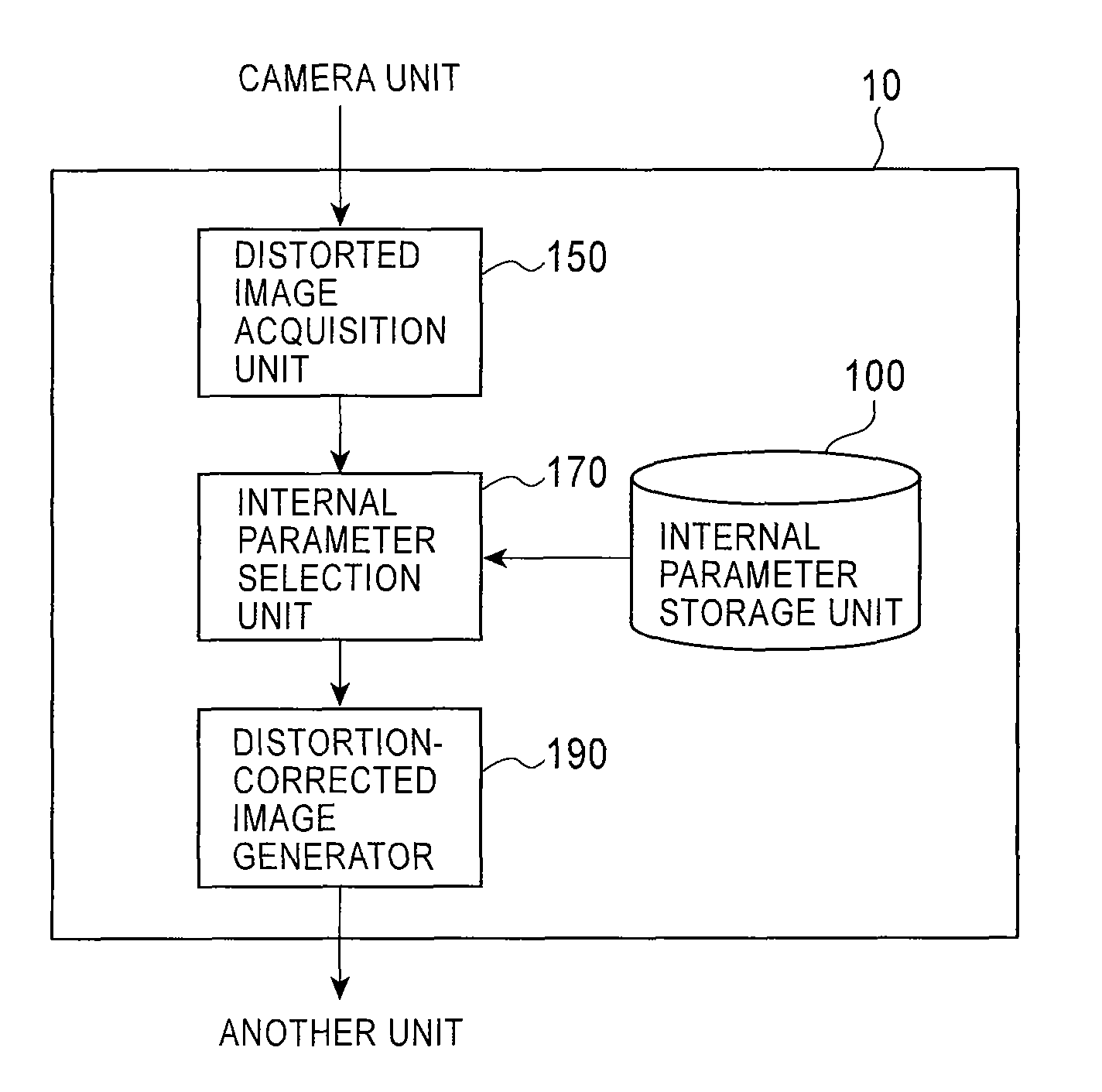
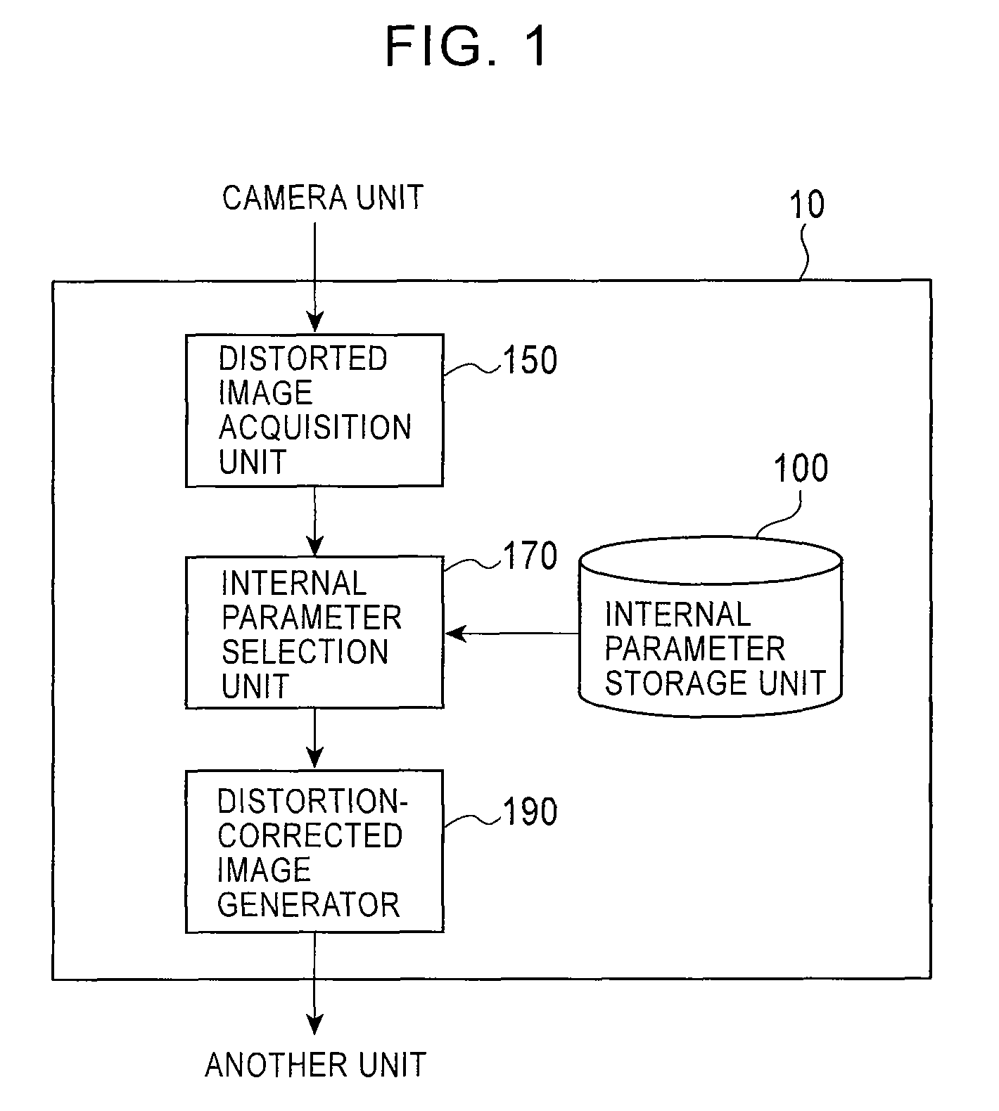
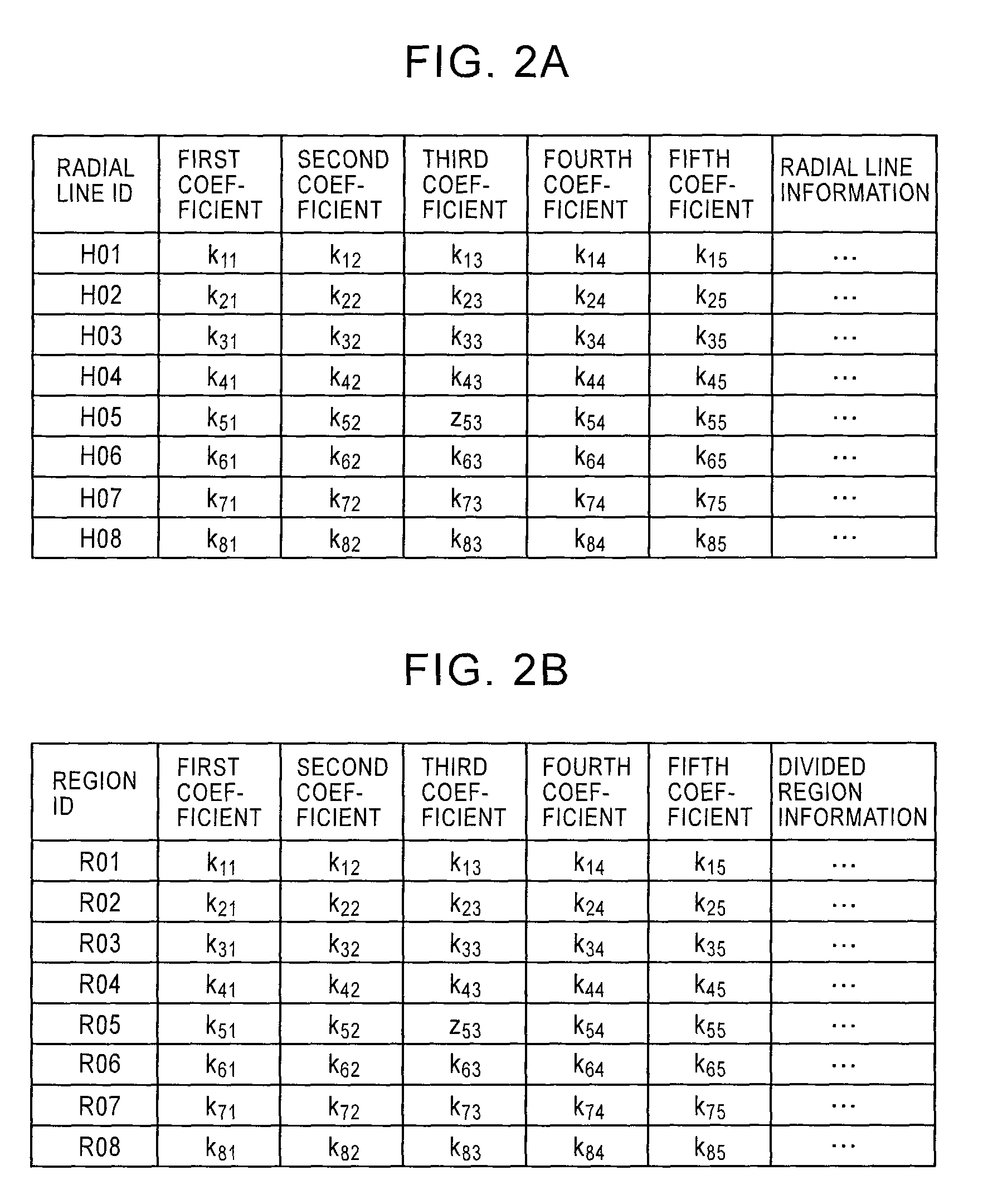
[0036]A first embodiment of the present invention will now be described with reference to the drawings. FIG. 1 shows exemplary components of a distortion-corrected image generation unit 10 according to the first embodiment of the present invention. FIGS. 2A and 2B show exemplary internal parameters stored in an internal parameter storage unit 100. FIGS. 3 and 4 illustrate the internal parameters stored in the internal parameter storage unit 100. In Part (a) of FIG. 3, reference letter R denotes the intersection of the XY plane and a vertical line that extends from a point Q on a line OP. Reference letter Φ denotes the angle between a line OY and a line OR. Reference letters XYZ, P, Θ, o, q, r denote the same components as in Part (a) of FIG. 23.

[0037]The distortion-corrected image generation unit 10 generates a distortion-corrected image by correcting the distortion of a distorted image captured using a fish-eye lens (the same applies to distortion-corrected image generation units 2...


PUM


Abstract

An internal parameter storage unit stores, in advance, a plurality of sets of internal parameters each of which can be applied to correct a pixel position in a direction from an image principal point, i.e., a plurality of sets of internal parameters for accommodating errors of different magnitudes that occur in individual directions from an image principal point. An internal parameter selection unit selects a set of internal parameters from the plurality of sets of internal parameters stored in advance on the basis of the direction of a pixel position to be corrected from the image principal point, and a distortion-corrected image generator corrects distortion on the basis of the selected set of internal parameters, so that, even when a surface of a lens is not exactly parallel to a surface of an image pickup device, distortion is corrected more accurately.

Description

BACKGROUND OF THE INVENTION[0001]1. Related Applications[0002]The present application claims priority to Japanese Patent Application Number 2007-313620, filed Dec. 4, 2007, the entirety of which is hereby incorporated by reference.[0003]2. Field of the Invention[0004]The present invention relates to distortion-corrected image generation units and distortion-corrected image generation methods, and in particular, relates to a distortion-corrected image generation unit and a distortion-corrected image generation method suitable for correcting the distortion of an image captured by a fish-eye lens.[0005]3. Description of the Related Art[0006]In general, distortion generated in an image captured using a lens, for example, a fish-eye lens (hereinafter called a distorted image), the focal length of which is short, is corrected using the internal parameters of the used lens. FIG. 23 is a schematic diagram showing known distortion correction. In Part (a) of FIG. 23, reference letters XYZ den...

Claims


Application Information

Patent Timeline
Patent Type & Authority Patents(United States)
IPC IPC(8): H04N9/64H04N5/217H04N5/225H04N5/232G02B5/32G06K9/40G06T3/00H04N1/387
CPCG06T3/0062H04N5/3572H04N5/217G06T5/006H04N23/81H04N25/61
Inventor IMAMURA, KOSUKE
Owner ALPINE ELECTRONICS INC
Why Eureka
Try Eureka