
Digital camera having panning and/or tilting functionality, and an image rotating device for such a camera

a technology of digital cameras and functionality, applied in the field of digital cameras having panning and/or tilting functionality, can solve the problems of large and expensive mechanics, slow speed at which the camera may be panned or tilted, and complex approaches, and achieve efficient and rapid panning and/or tilting, and the effect of fast and more accurate panning and/or tilting

Inactive Publication Date: 2007-08-14
AXIS
View PDF22 Cites 16 Cited by
  • Summary
  • Abstract
  • Description
  • Claims
  • Application Information

AI Technical Summary

Benefits of technology

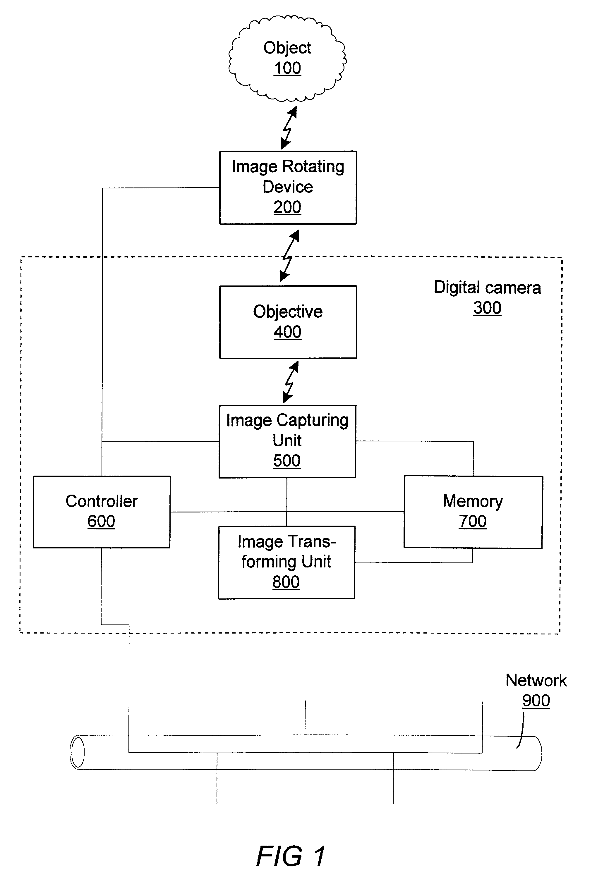
[0004]It is an object of the present invention to provide a digital camera, which allows faster and more accurate panning and / or tilting, thereby allowing the camera to produce more images per time unit. Furthermore, it is an object of the present invention to provide an image rotating device, to be mounted externally to the digital camera, for providing efficient and rapid panning and / or tilting funtionality, without requiring large or expensive mechanics.

Problems solved by technology

Since the camera and objective have a considerable weight, such an approach involves complex, large and expensive mechanics.
Furthermore, the speed at which the camera may be panned or tilted is restricted due to the large mass, that has to be moved accordingly.

Method used


Image

  • Digital camera having panning and/or tilting functionality, and an image rotating device for such a camera
  • Digital camera having panning and/or tilting functionality, and an image rotating device for such a camera
  • Digital camera having panning and/or tilting functionality, and an image rotating device for such a camera

Examples


Embodiment Construction

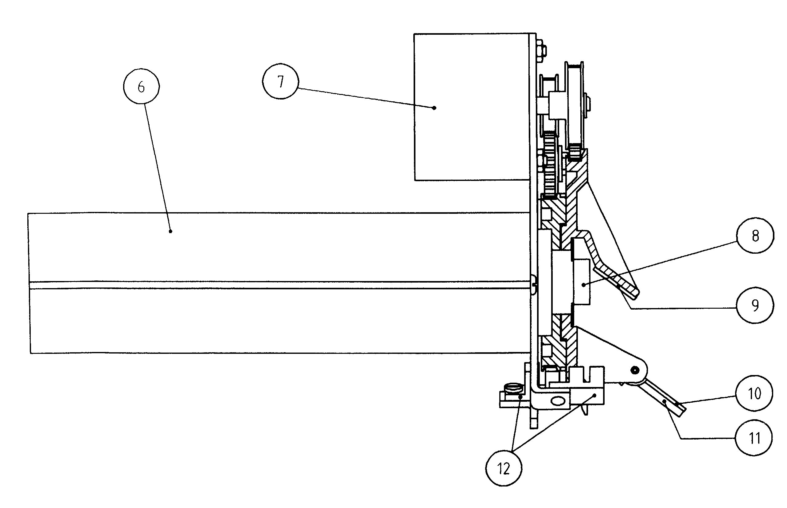
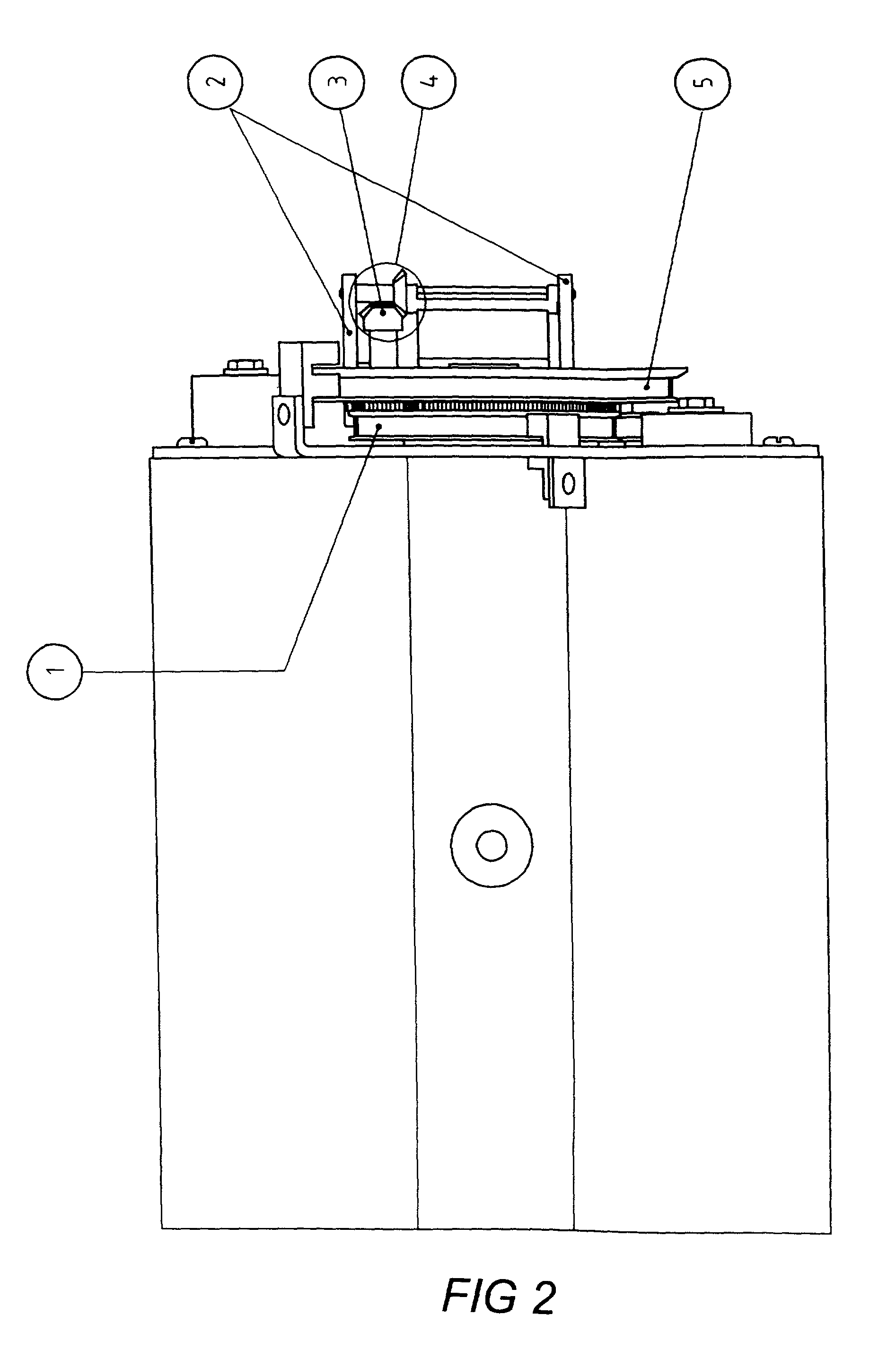
[0012]Referring to FIG. 1, a digital camera 300 is illustrated in a basic modular form. The digital camera 300 is arranged to produce one or several digital image(s) of a generic object 100, which may be any physical object that is present in a volume optically covered by the digital camera 300. An inventive image rotating device 200 is mounted externally to the digital camera 300 in front of an optical input 400 of the digital camera. The optical input 400 is a generally known lens or objective. The purpose of the image rotating device 200 is to extend the available field of view of the digital camera 300 in at least one plane, preferably in a horizontal plane as well as in a vertical plane. A preferred embodiment of the image rotating device 200 will be described in more detail with reference to FIGS. 2-4.

[0013]As shown in FIG. 1, the digital camera 300 further comprises an image capturing unit 500, which is provided with appropriate means for producing a digital image representat...


PUM


Abstract

A digital camera (300) has panning and / or tilting functionality and comprises: a camera housing (6) with an optical input (400), such as a lens or objective (8); an image capturing unit (500) for producing a digital image from light received through the optical input; and a controller (600). A first mirror (9) is mounted externally to the camera housing (6). An image rotating device (200) receives an angular displacement control signal from the controller (600) and rotates the first mirror at an angle with respect to the optical input (400, 8) of the camera housing (6).

Description

TECHNICAL FIELD[0001]The present invention relates to a digital camera having panning and / or tilting functionality, and more specifically to a digital camera having a camera housing with an optical input, such as a lens or objective, an image capturing unit and a controller. The invention also relates to an image rotating device for providing the panning and / or tilting functionality of such a digital camera.BACKGROUND ART[0002]A common example of a digital camera with panning and / or tilting functionality is a web camera, which e.g. may be mounted at a given location for the purpose of surveillance, production monitoring, etc. The web camera comprises an optical input in the form of a lens or objective and an image capturing unit for producing a digital image from light received from the optical input. Usually, the image capturing unit comprises a CCD element (Charge Coupled Device). The web camera has software and hardware for allowing the camera to be connected to a given network, ...

Claims


Application Information

Patent Timeline
IPC IPC(8): H04N5/225H04N7/00
CPCG03B17/02H04N5/2259H04N23/58
Inventor SAGEFALK, WILLYABRAHAMSSON, LARS
Owner AXIS
Learn More