Stabilization of three-dimensional images in a scannerless range imaging system

a scannerless range and imaging system technology, applied in the field of digital image processing, can solve the problems of complex systems, high cost, and inability to accurately form three-dimensional images, and achieve the effect of tolerant at least a small degree of global movemen

Active Publication Date: 2005-08-02
MONUMENT PEAK VENTURES LLC
View PDF7 Cites 19 Cited by
  • Summary
  • Abstract
  • Description
  • Claims
  • Application Information

AI Technical Summary

Benefits of technology

[0011]The invention has the advantages of correcting unwanted motion if that motion is small, and of removing one or more phase offset images from the image bundle if that image motion is large or localized, without incurring the penalty of having to capture more images to repopulate the image bundle if motion is observed in the captured images. Since use of the method effectively tolerates at least a small degree of global movement, the invention will also allow for range collection using cameras that lack sources of firm support, e.g., handheld cameras.

Problems solved by technology

However, if the collection of phase offset images is captured while the SRI system is held in the hands of the photographer, the slightest jitter or movement of the hands may introduce stabilization errors that will adversely affect the formation of the three-dimensional image.
For another example of unwanted motion, consider that the collection of phase offset images is captured by a film SRI system, such as the system described in commonly assigned U.S. Pat. No. 6,118,946, “Method and apparatus for scannerless range image capture using photographic film.” When the phase offset images are scanned, film positioning errors can contribute to an incorrect formation of the three-dimensional image.
However, these systems are often complex and expensive.
In the presence of significant local motion, such as multiple objects moving with independent motion trajectories, these methods may fail due to the computation of erroneous global motion parameters.
In addition, it may be difficult to apply these methods to a sequence of phase offset images because the intensity value at each pixel depends in part on the phase offsets used to capture each image.
However, these methods only apply to sequences that have no local motion, or alternatively, a user must select a region in consecutive frames that has no local motion.
The dependence upon areas with no local motion and the necessity for user intervention are major drawbacks of these methods.
Therefore, an additional drawback to all of the aforementioned methods is that there exist no mechanisms for selectively removing or ignoring any frames where the unwanted motion is deemed severe.
If the unwanted motion is too large or localized in any of the phase offset images, any errors introduced by the removal method degrade the resulting three-dimensional image to a quality lower than it would have been had the corresponding phase offset images been ignored.

Method used


Image

  • Stabilization of three-dimensional images in a scannerless range imaging system
  • Stabilization of three-dimensional images in a scannerless range imaging system
  • Stabilization of three-dimensional images in a scannerless range imaging system

Examples


Embodiment Construction

[0018]Because range imaging devices employing laser illuminators and capture devices (including image intensifiers and electronic sensors) are well known, the present description will be directed in particular to elements forming part of, or cooperating more directly with, a method and / or system in accordance with the present invention. Elements not specifically shown or described herein may be selected from those known in the art. Certain aspects of the embodiments to be described may be provided in software. Given the system as shown and described according to the invention in the following materials, software not specifically shown, described or suggested herein that is useful for implementation of the invention is conventional and within the ordinary skill in such arts.

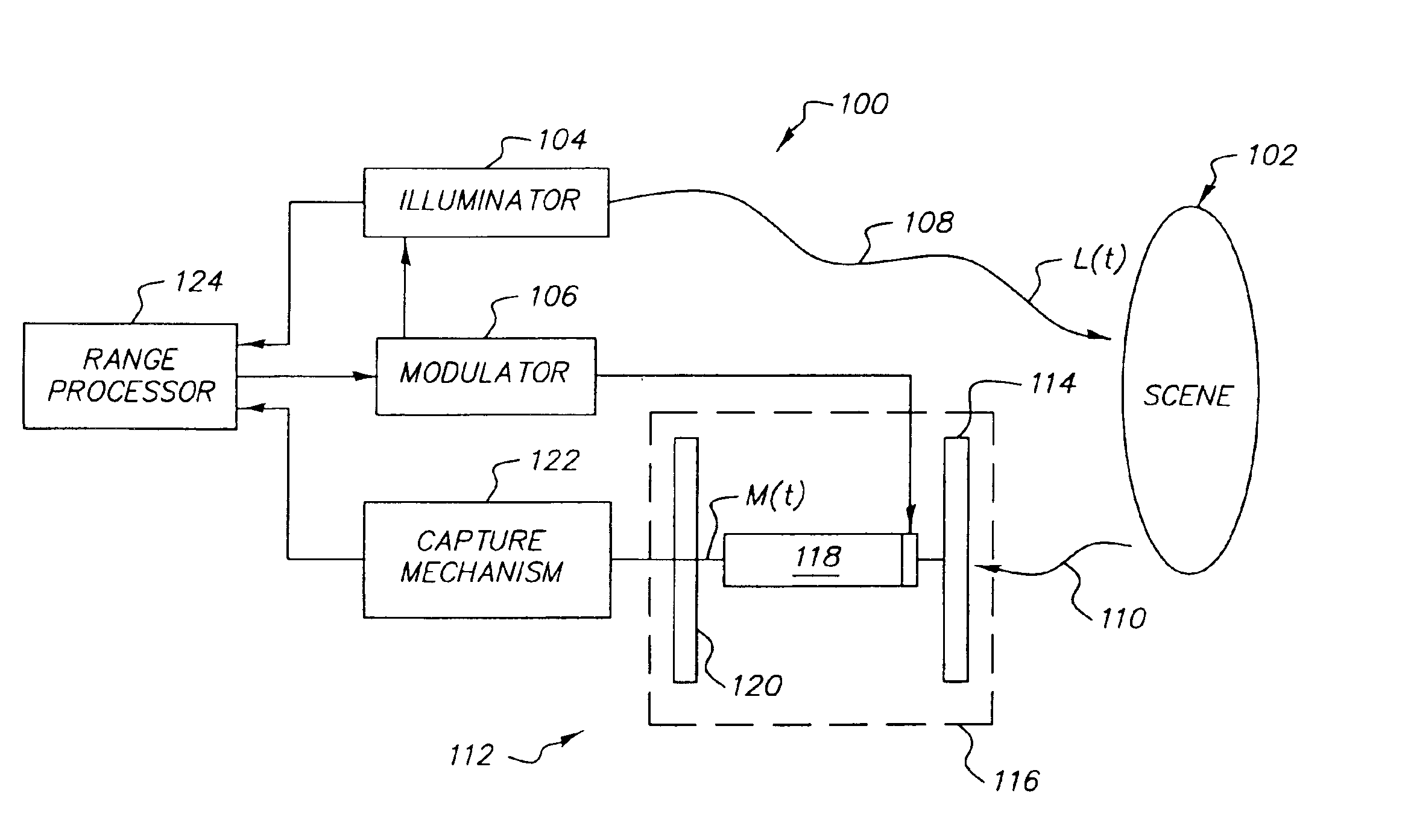
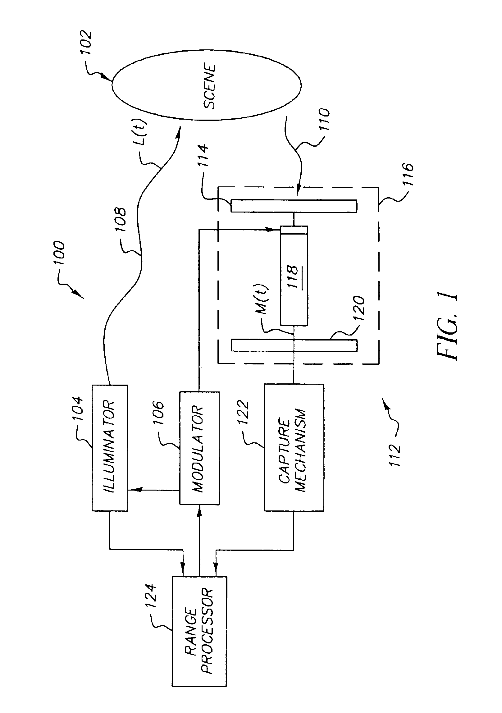
[0019]It is helpful to review the principles and techniques involved in scannerless range imaging. Accordingly, referring to FIG. 1 (prior art), an SRI camera 100 is shown as a laser radar that is used to illumina...


PUM


Abstract

A method for generating a stabilized three-dimensional image from a scannerless range imaging system comprises the steps of acquiring a bundle of three or more phase offset images corresponding to modulated illumination reflected from a scene, whereby one or more of the phase offset images includes image motion relative to another phase offset image; searching for a stable chain of phase offset images in the image bundle, wherein a stable chain is a collection of images that is obtained by testing the phase offset images against a confidence measure that separates less severe correctable image motion from more severe image motion and then populating the stable chain only with those phase offset images that meet the confidence measure for correctable image motion; correcting for the image motion in the stable chain of images if a stable chain of at least three phase offset images is found to exist; and computing a stabilized three-dimensional image using the phase offset images from the stable chain of phase offset images.

Description

FIELD OF THE INVENTION[0001]The invention relates generally to the field of digital image processing, and in particular to a technique for compensating for stabilization errors in the formation of a three-dimensional image from an image bundle captured from a scannerless range imaging system.BACKGROUND OF THE INVENTION[0002]U.S. Pat. No. 4,935,616 (further described in the Sandia Lab News, vol. 46, No. 19, Sep. 16, 1994) describes a scannerless range imaging system using either an amplitude-modulated high-power laser diode or an array of amplitude-modulated light emitting diodes (LEDs) to completely illuminate a target scene. An improved scannerless range imaging system that is capable of yielding color intensity images in addition to the 3D range images is described in commonly-assigned, U.S. Pat. No. 6,349,174 entitled “Method and Apparatus for a Color Scannerless Range Imaging System”. As used herein, a scannerless range imaging system will be referred to as a “SRI system”. In th...

Claims


Application Information

Patent Timeline
Patent Type & Authority Patents(United States)
IPC IPC(8): G01S17/89G01S17/00H04N5/232G01S7/48G01S7/36G01S7/497G01S17/36G06T7/20
CPCG01S17/89G06T7/20H04N5/23248H04N5/23264G01S7/497G01S17/36H04N23/68H04N23/682
Inventor CAHILL, NATHAN D.RAY, LAWRENCE A.REVELLI, JR., JOSEPH F.
Owner MONUMENT PEAK VENTURES LLC
Why Eureka
Try Eureka