Fuel System for Vehicle with Engine

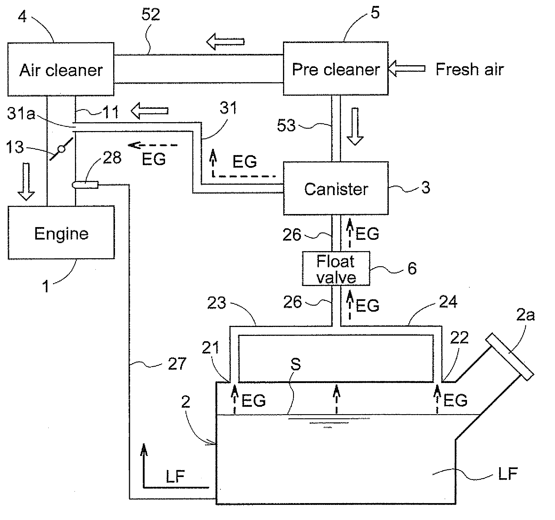
a fuel system and engine technology, applied in the direction of condensed fuel collection/return, charge feed system, non-fuel substance addition to fuel, etc., can solve the problem that 3/b> may disadvantageously be soaked with liquid fuel lf, and achieve simple and low-cost structure and high reliability

Active Publication Date: 2010-08-19
KUBOTA LTD
View PDF1 Cites 13 Cited by
  • Summary
  • Abstract
  • Description
  • Claims
  • Application Information

AI Technical Summary

Benefits of technology

[0006]In view of the above, the object of the present invention is to provide a fuel system with a simple and low-cost structure for adjusting the emission amount of the fuel vapor to the atmosphere with high reliability, while retaining the function of the canister.
[0009]In short, in the fuel system according to the present invention, even when the fuel tank is inclined at least one of the longitudinal and lateral directions, the fuel vapor generated in the fuel tank is sent to the canister, and thus the inner pressure of the fuel tank will not be increased. As a result, a risk of the liquid fuel entering the canister can be surely suppressed. In spite of the simple and low-cost structure, the fuel system according to the present invention retains the excellent function of the canister and complies with the regulations for fuel vapor emission, even when the work vehicle is in an inclined state.
[0012]Typically, when the engine is operated with a lower load, an air-fuel ratio is set on a lean side, which is near an ideal air-fuel ratio, for the purpose of improving fuel consumption. However, when an unnecessary fuel vapor is discharged to the air-intake path to the engine, incomplete combustion occurs and CO or the like is generated. For this reason, the emission amount of the fuel vapor is electronically controlled in accordance with an operational condition of the engine. It should be noted that, even when the engine is operated with a higher load, introduction of some fuel vapor does not cause any problem, since the air-fuel ratio is originally set on a rich side.
[0013]When the engine is operated with a lower load, an opening degree of the on-off valve becomes small, and thus an intake volume to the engine is suppressed. When the engine performs an air-intake step, a negative pressure is exerted at a point in the air-intake path downstream of the on-off valve, i.e., on an engine side. However a portion of the air-intake path upstream of the on-off valve is not likely to be affected by the air-intake step of the engine, and thus a degree of the negative pressure is smaller as compared with the downstream side.
[0014]Like this preferable embodiment, when the fuel vapor adsorbed to the canister is released to a point in the air-intake path upstream of the on-off valve, the upstream side is not likely to be affected by the negative pressure during a low-load operation of the engine. In addition, since the opening degree of the on-off valve is small, entry of the fuel vapor into a point downstream of the on-off valve in the air-intake path is suppressed. Therefore, introduction of an unnecessary fuel vapor to the engine can be suppressed. On the other hand, during a high-load operation in which the opening degree of the on-off valve is large, the air-intake path opens wide, and the most of the fuel vapor, together with the intake air, is introduced to the engine. However, as described above, introduction of some fuel vapor does not cause any problem, since an air-fuel ratio is set on a rich side. In this manner, while retaining the normal function of the canister, by utilizing the negative pressure on the engine side, the emission amount of the fuel vapor can be adjusted in accordance with the operational conditions of the engine, with a simple and low-cost structure.

Problems solved by technology

As a result, the liquid fuel LF may reach the canister 3 along the pipe and the canister 3 may disadvantageously be soaked with the liquid fuel LF.

Method used


Image

  • Fuel System for Vehicle with Engine
  • Fuel System for Vehicle with Engine
  • Fuel System for Vehicle with Engine

Examples


Embodiment Construction

[0032]Hereinbelow, preferred embodiments of the present invention will be described with reference to the accompanied drawings. Features of one embodiment can be used in combination with features of another embodiment, and such combinations are encompassed in the scope of the present invention, as long as the combination does not create inconsistency.

[0033]Hereinbelow, an embodiment of the fuel system according to the present invention will be described with reference to the drawings, while illustrating a utility vehicle (hereinafter, simply referred to as “UV”) having an engine using gasoline as fuel, to which the fuel system is applied.

(Entire Configuration)

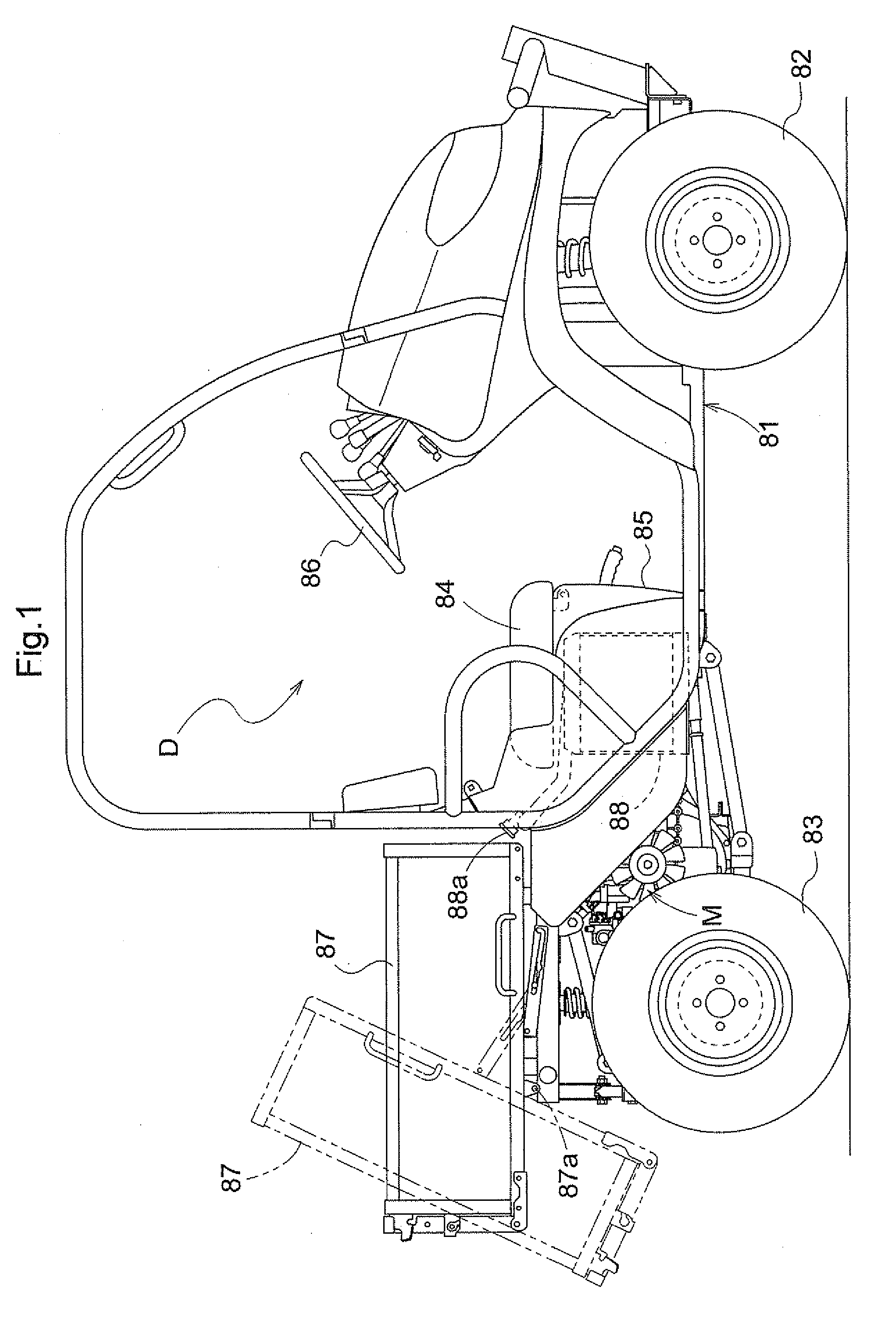
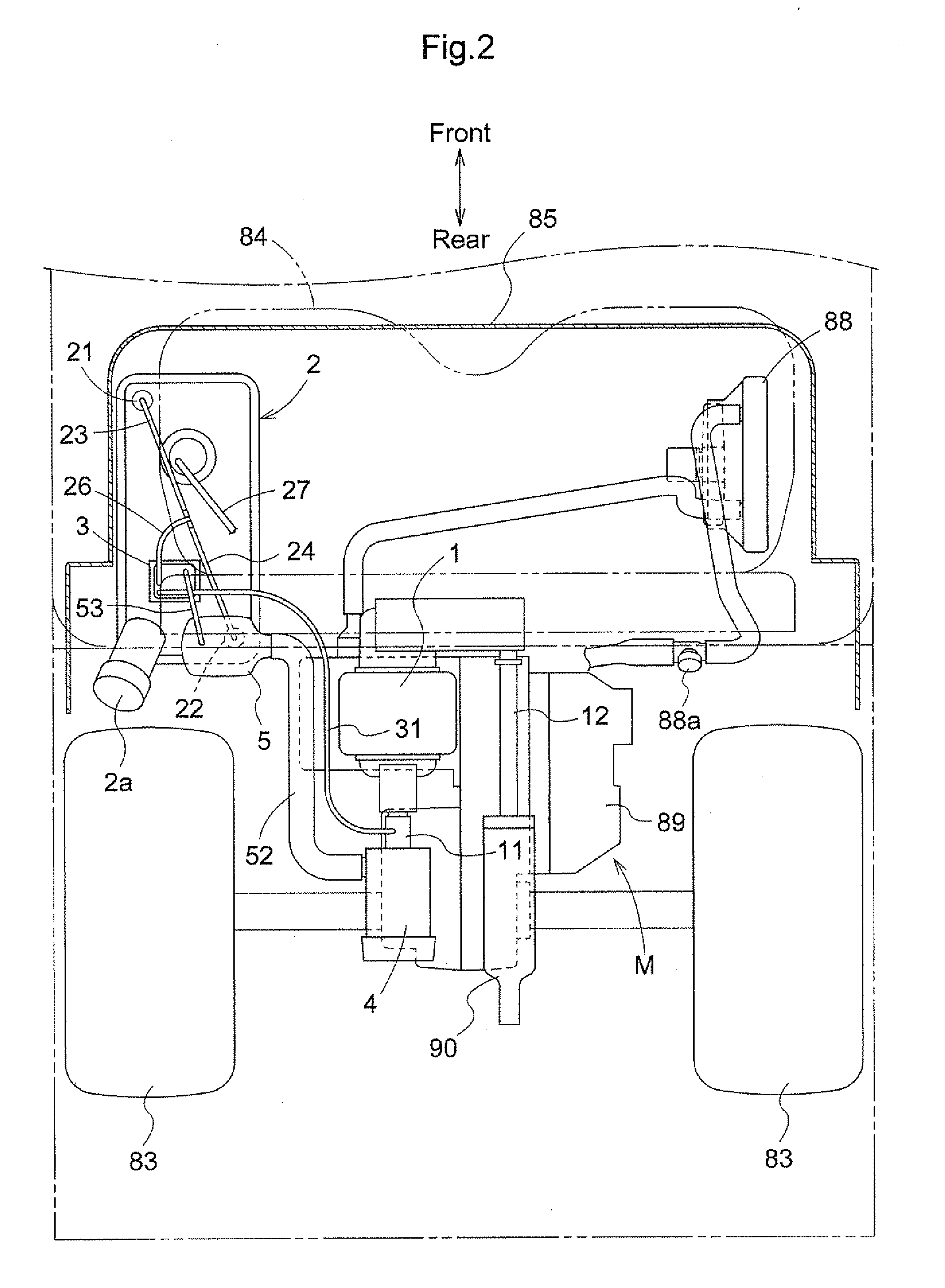
[0034]As shown in FIGS. 1 and 2, the UV has a pair of right and left steerable front wheels 82 and a pair of right and left rear wheels 83. The front and rear wheels 82,83 are disposed on front and rear portions of a body frame 81, respectively. Between the front and rear wheels 81,82, a driver's cabin D and a motor part M are ...


PUM


Abstract

A fuel system for a vehicle with an engine includes: a fuel tank for storing fuel: first and second ports disposed on a wall of the fuel tank, between which wall and a fuel fluid level a clearance is created when the fuel is contained in an allowable maximal amount in the fuel tank of the vehicle in a horizontal state, the first and second ports being positioned frontward and rearward, respectively, in a longitudinal direction of the vehicle, and the first port and the second port being out of alignment in a lateral direction; a canister for adsorbing and releasing a fuel vapor; an inflow line for sending the fuel vapor generated in the fuel tank to the canister through the first and second ports; and a discharge line for sending the fuel vapor from the canister to an air-intake path to the engine.

Description

BACKGROUND OF THE INVENTION[0001]1. Field of the Invention[0002]The present invention relates to a fuel system for a vehicle with an engine, particularly to a fuel system which has a canister for adsorbing a fuel vapor (evaporated gas) generated in a fuel tank, and discharges the fuel vapor adsorbed to the canister to an air-intake path leading to the engine.[0003]2. Description of the Related Art[0004]In order to comply with regulations for fuel vapor emission, there has been known a fuel system which has a canister for adsorbing a fuel vapor from a fuel tank and discharges the fuel vapor adsorbed to the canister to an air-intake path leading to the engine, as disclosed in Japanese patent application JP2008-144607A (see paragraphs 0038 and 0039 and FIG. 3) and Japanese patent application JPS-332207A (see paragraphs 0016 to 0018 and FIG. 2). In the vehicles to which such a fuel system is applied, the fuel vapor whose emission amount is set in accordance with operational conditions o...

Claims


Application Information

Patent Timeline
Patent Type & Authority Applications(United States)
IPC IPC(8): F02M33/02
CPCF02M25/089
Inventor ISHIDA, YUUKISHIMADA, HIROSHI
Owner KUBOTA LTD
Why Eureka
Try Eureka