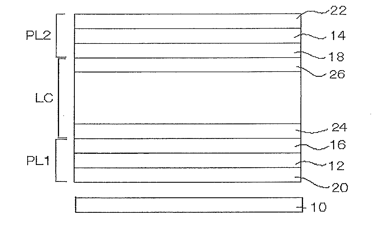
[0214]Assiduous investigations made by the present inventors have revealed that the effect of the invention is especially remarkable in an embodiment where the ratio of the part contrast of the front-side substrate (including the substrate 26 in FIG. 1 and all the parts formed on the substrate) (CRf) to the part contrast of the rear-side substrate a VA
liquid crystal cell (including the substrate 24 in FIG. 1 and all the parts formed on the substrate) (CRr)(CRf / CRr) is from 0.3 to 2.8, or that is, CRf / CRr is from 0.3 to 2.8. In this, when the VA-mode
liquid crystal cell (LC in FIG. 1) is disassembled into two substrates (substrates 24 and 26 in FIG. 1), the front-side substrate (substrate 26 in FIG. 1) and the parts formed on the substrate are generically referred to as the front-side substrate; and the rear-side substrate (substrate 24 in FIG. 1) and the parts formed on the substrate are generically referred to as the rear-side substrate. Examples of the parts include color filter,
black matrix, array part (TFT array, etc.), projections on the substrate, common
electrode, slits, etc. Specifically, the part contrast of the rear-side substrate of a
liquid crystal cell and that of the front-side substrate thereof each mean the total contrast of the substrate and the parts formed on the substrate. The details of the measurement method are described in Examples given below.
[0215]Assiduous investigations made by the present inventors have revealed that the retardation of the first retardation region between the rear-side polarizing element and the liquid
crystal cell has a significant influence on the front CR of the
liquid crystal display device. The reason is because the
optical phenomena such as scattering and
diffraction occurring in the parts of the liquid
crystal cell (for example, liquid
crystal layer, color filter,
black matrix, array part, projections formed on the substrate, common
electrode part, slit part, etc.) have polarization dependency. The details are described below.
[0216]In general, in the VA-mode liquid
crystal display device, the liquid crystal layer is in a
vertical alignment state at the time of
black level of display, and therefore, the linear polarized light having passed through the rear-side polarizing element and running toward the normal direction at that time does not change its polarization state even after it has passed through the liquid crystal layer, and in principle, the light is all absorbed by the absorption axis of the front-side polarizing element. Specifically, in principle, it may be said that there occurs no light leakage in the normal line direction at the time of
black level of display. However, the front
transmittance at the time of black level of display of the VA-mode liquid
crystal display device is not zero. It is known that one reason is because the liquid crystal molecules in the liquid crystal layer fluctuate, and the light having come into the liquid crystal layer is scattered in some degree by the fluctuation. When the light having come into the liquid crystal layer contains completely only the linear polarized component to be absorbed at the absorption axis of the front-side polarizing element, the influence may be greater and the light leakage on the front tends to increase. Specifically, when the retardation in the retardation region arranged on the rear side is larger and when the incident light is elliptically polarized at a higher
elliptical polarization degree, then the light leakage on the front owing to the fluctuation can be reduced more.
[0217]However, as a result of assiduous investigations, the present inventors have known that, except the fluctuation of the liquid crystal molecules in the liquid crystal layer, the retardation in the retardation region between the rear-side polarizing element and the liquid crystal layer also contributes to the reason for light leakage. When the oriented light from the backlight has passed through the rear-side polarizing element and comes in the retardation region in an oblique direction, the linear polarized light is converted into elliptical polarized light owing to the retardation. The elliptically-polarized light is diffracted and scattered in the array part of the liquid
crystal cell and in the color filter layer, and at least a part of the light comes to run in the front direction. The
elliptically polarized light includes a linear polarized light component that could not be blocked at the absorption axis of the front-side polarizing element, and therefore, even at the time of black level of display, there occurs light leakage in the front direction, therefore causing a reason for front CR reduction. The
optical phenomena to occur through the array part and the color filter layer are, for example, because the surface of the array part and the color filter layer is not completely smooth but is roughened in some degree and because the part may contain some scattering factors, etc. The influence of the
optical phenomena to occur through the array part and the color filter layer on the light leakage in the front direction is greater than the influence thereon of the fluctuation of the liquid crystal molecules in the liquid crystal layer mentioned above.
[0218]As a result of further investigations, the present inventors have known that the optical phenomena (
diffraction, scattering, etc.) to occur when the light elliptically polarized through the retardation region passes through the predetermined parts of the liquid
crystal cell bring about different influence
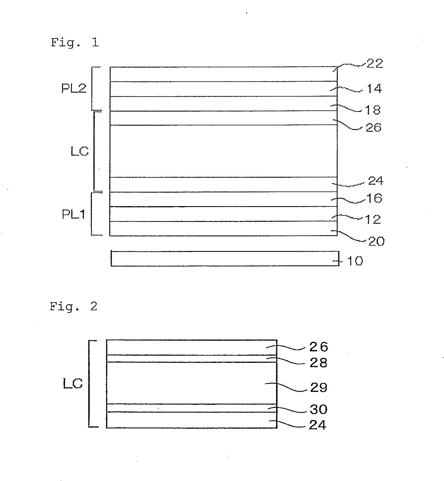
modes on the light leakage in the front direction depending on as to whether the light passes through the part before coming into the liquid crystal part or the light passes through the part after having passed through the liquid crystal layer. In FIG. 1, for example, when an array part is disposed on the inner face of the rear-side substrate 24 and a color filter is disposed on the inner face of the front-side substrate 26 as in FIG. 2, the incident light passes through the array part before coming into the liquid crystal layer, and after having passed through the liquid crystal layer, it runs through the color filter.
[0219]In the part through which the incident light passes before coming into the liquid crystal layer (e.g., array part), the degree of
elliptical polarization of the incident light is determined by the retardation in the rear-side retardation region (first retardation region) through which the light passes beforehand. On the other hand, in the part through which the incident light passes after having passed through the liquid crystal layer (e.g., color filter), the degree of
elliptical polarization of the incident light is determined by the retardation of the liquid crystal layer in addition to the retardation in the rear-side retardation region. In the case of a VA-mode liquid
crystal display device, in general, Δnd(590) of the liquid crystal layer is defined to be from 280 to 350 nm or so. d means the thickness of the liquid crystal layer (nm); Δn(λ) means the refractivity
anisotropy at a
wavelength λ of the liquid crystal layer; and Δnd(2) is the product of Δn(λ) and d. Even though the retardation in the rear-side retardation region is so defined that the light leakage through the array part is reduced, the degree of elliptical polarization rather increases contrary to this, after the incident light has passed through the liquid crystal. When the retardation in the rear-side retardation region is larger, then the degree of elliptical polarization of the incident light is smaller, and therefore, depending on the part through which the incident light passes before passing through the liquid crystal layer or on the part through which the incident light passes after having passed through the liquid crystal layer, the effect for the influence of the part on the light leakage in the front direction is turned back.


