
System, method, and apparatus for monitoring power

a technology of power monitoring and apparatus, applied in the direction of nuclear engineering, electric devices, nuclear elements, etc., can solve the problems of affecting the efficiency at which power is applied, unable to obtain a good estimate of load impedance, and often difficult, if not impossible, to average forward voltage or reflected voltage measurements

Inactive Publication Date: 2011-06-28
ADVANCED ENERGY IND INC
View PDF58 Cites 20 Cited by
  • Summary
  • Abstract
  • Description
  • Claims
  • Application Information

AI Technical Summary

Benefits of technology

The present invention provides a system, method, and apparatus for monitoring a processing system by measuring RF power applied to a plasma load and analyzing the resulting data. This analysis includes obtaining N parameter-value pairs, calculating an average reflection coefficient, and using the average reflection coefficient to manage the processing system. The technical effect of the invention is to provide a more accurate and efficient means for monitoring and controlling processing systems.

Problems solved by technology

And the impedance of the plasma load affects the efficiency at which power is applied from the generator to the load.
Obtaining a good estimate of load impedance, however, is often difficult.
As a consequence, it is very difficult, if not impossible, to average either the forward voltage or the reflected voltage measurements (e.g., to remove noise and unwanted modulation).
Problematically, each time a reflection coefficient is calculated in this manner, system resources are utilized; thus this approach to obtaining an average reflection coefficient is computationally intensive and is prone to excessive utilization of system resources.
As a consequence, known techniques are often too inefficient to provide desirable information about the electrical characteristics of plasma loads.

Method used


Image

  • System, method, and apparatus for monitoring power
  • System, method, and apparatus for monitoring power
  • System, method, and apparatus for monitoring power

Examples


Embodiment Construction

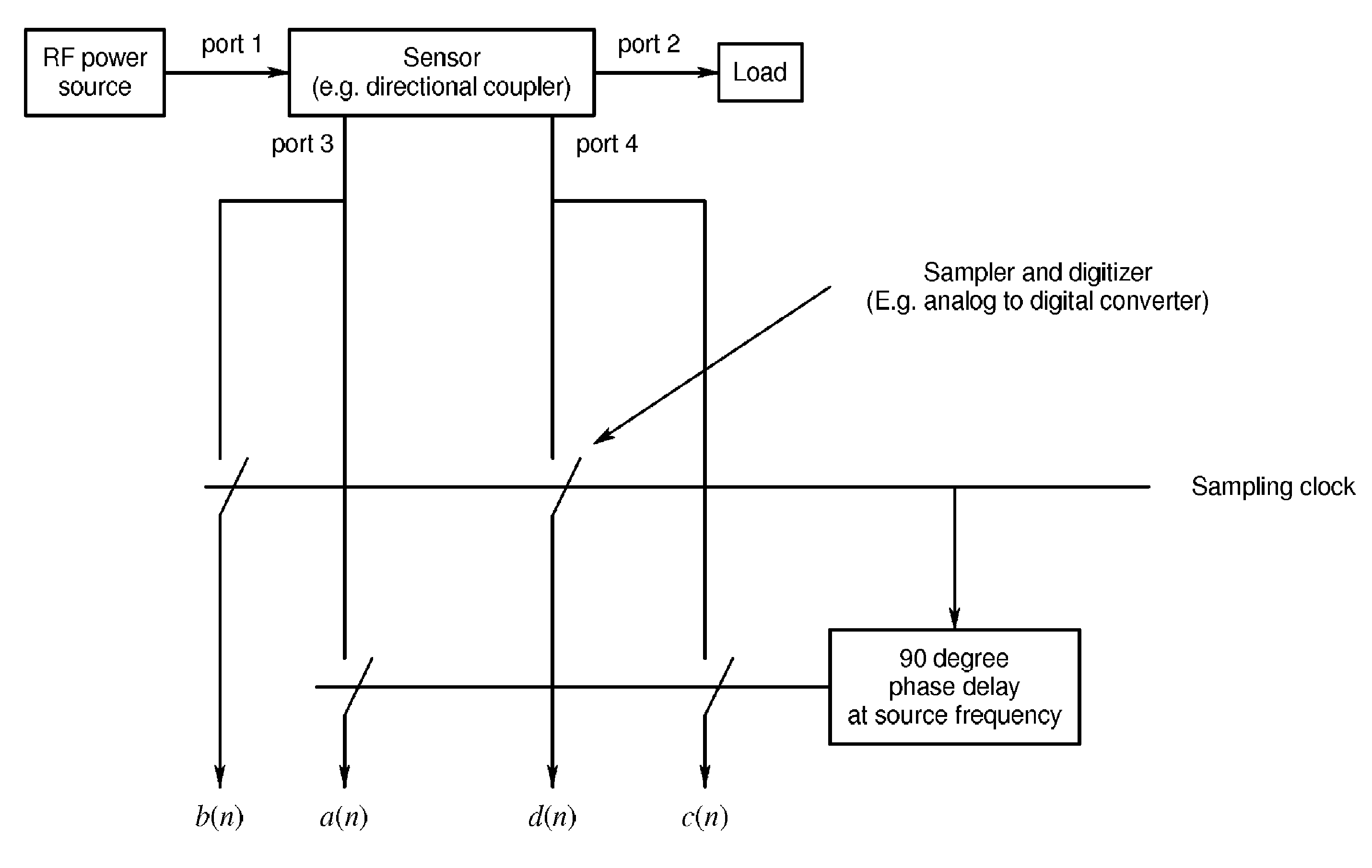
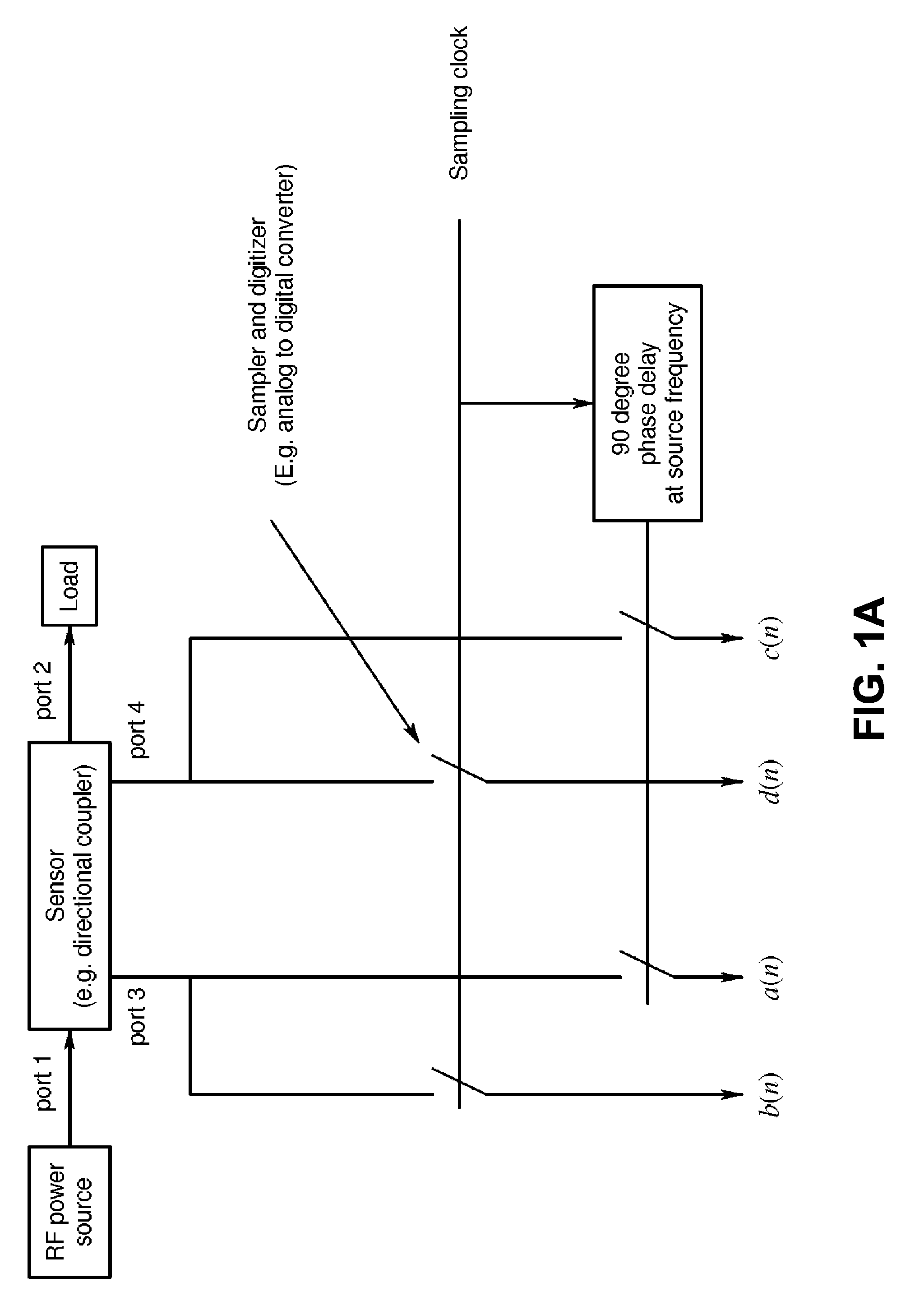
[0026]Referring now to the drawings, where like or similar elements are designated with identical reference numerals throughout the several views, and referring in particular to FIG. 2, it is a block diagram depicting a plasma processing environment 100 in which several embodiments of the invention may be implemented. As shown, a radio frequency (RF) generator 102 is coupled to a plasma chamber 104 via an impedance matching network 106, and an analysis portion 108 is disposed to receive an input from a first sensor 110 that is coupled to an output of the RF generator 102 and in input from a second sensor 112 that is coupled to an input of the plasma chamber 104. As depicted, the analysis portion 108 is also coupled to a man-machine interface 114, which may include a keyboard, display and pointing device (e.g., a mouse).

[0027]The illustrated arrangement of these components is logical and not meant to be an actual hardware diagram; thus, the components can be combined or further separ...


PUM

PropertyMeasurementUnit
frequenciesaaaaaaaaaa
monitoring poweraaaaaaaaaa
reflection coefficientaaaaaaaaaa

Abstract

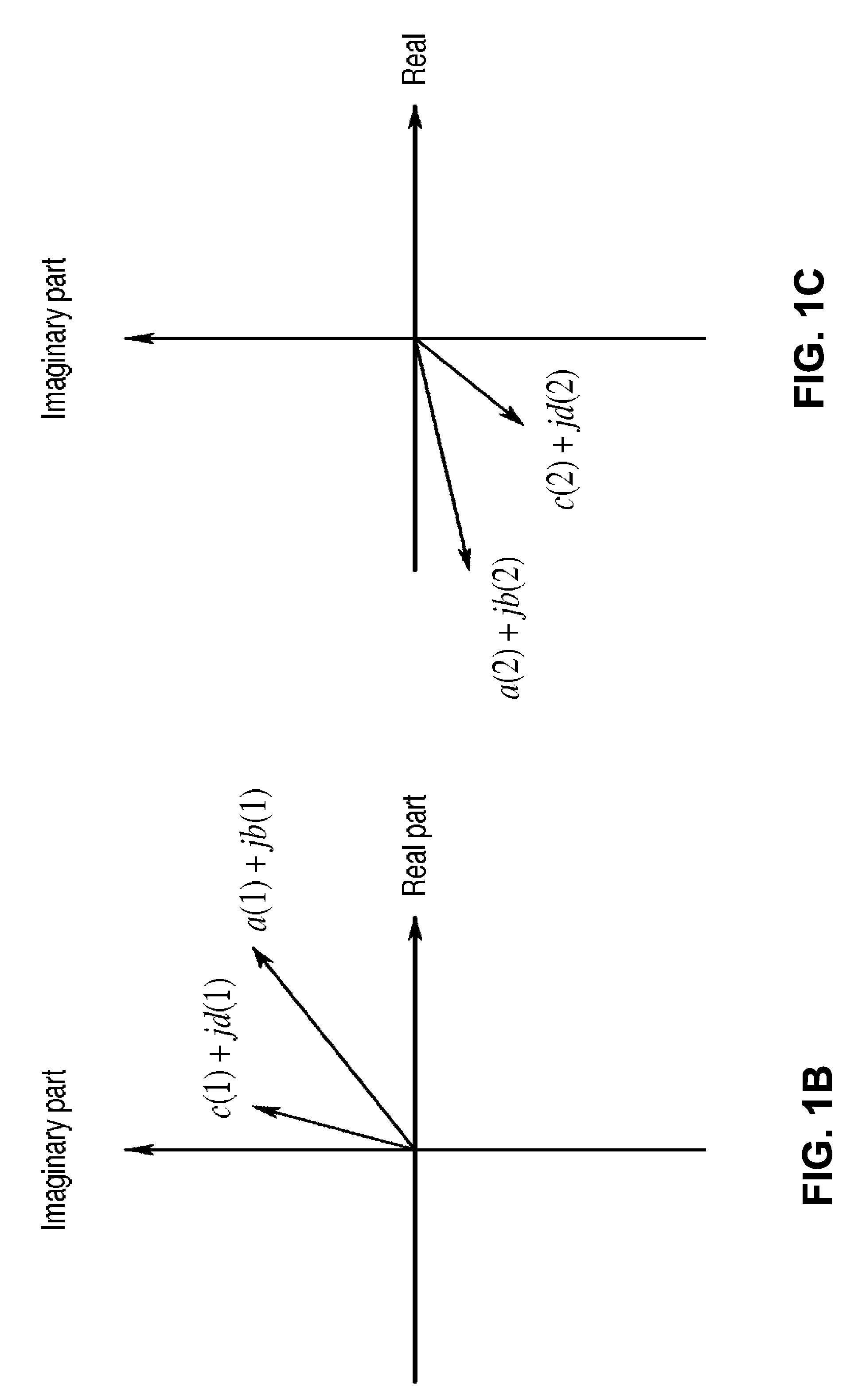
A system, method and apparatus for monitoring a processing system is disclosed. The method includes obtaining N parameter-value pairs that include a first parameter value and a second parameter value; obtaining, for each parameter-value pair, the product of the first parameter value and the complex conjugate of the second parameter value to obtain N products defined by a real part and an imaginary part; obtaining, for each parameter-value pair, a product of the second parameter value and the complex conjugate of the second parameter value to obtain N real numbers; calculating an average reflection coefficient by dividing an imaginary number by an average of the N real numbers, the real component of the imaginary number being equal to the average of the real parts of the N products and the imaginary part of the imaginary number being equal to an average of the imaginary parts of the N products.

Description

FIELD OF THE INVENTION[0001]This invention relates generally to apparatus and methods for plasma processing, and more particularly to apparatus and methods for monitoring parameters of plasma processing systems.BACKGROUND OF THE INVENTION[0002]In plasma processing applications, such as the manufacture of semiconductors or flat panel displays, RF power generators apply a voltage to a load in a plasma chamber and may operate over a wide range of frequencies. The impedance of a processing plasma can vary with the frequency of this applied voltage, chamber pressure, gas composition, and the target or substrate material. And the impedance of the plasma load affects the efficiency at which power is applied from the generator to the load. Consequently, an estimate of the plasma load impedance is a parameter that is often desirable for users to have available.[0003]Obtaining a good estimate of load impedance, however, is often difficult. For example, accurate measurements of forward and ref...

Claims


Application Information

Patent Timeline
Patent Type & Authority Patents(United States)
IPC IPC(8): G01R21/00
CPCG01R19/0007G01R27/32G01R21/01G01R21/001
Inventor VAN ZYL, GIDEON J.
Owner ADVANCED ENERGY IND INC
Learn More