Anchoring device

a technology of an anchoring device and a mounting plate, which is applied in the direction of door/window protection devices, shutters/movable grilles, building repairs, etc., can solve the problems of unintentional selection and mounting of the wrong type, waste of manufacturer or environmental resources, and inconvenience for users

Inactive Publication Date: 2011-07-05
HUNTER DOUGLAS IND BV
View PDF14 Cites 15 Cited by
  • Summary
  • Abstract
  • Description
  • Claims
  • Application Information

AI Technical Summary

Benefits of technology

[0007]It is an objective of the present invention to provide an improved anchoring device that can be attached to a surface irrespective of the orientation of the surface. It is a further object of the present invention to overcome or ameliorate at least one of the disadvantages of the prior art. It is also an object of the present invention to provide alternative anchoring devices which are less cumbersome in assembly and operation and which moreover can be made relatively inexpensively. Alternatively it is an object of the invention to at least provide the public with a useful choice.
[0008]To this end, the invention provides a device for anchoring an elongate guide element of an architectural covering, the anchoring device including a body having a rear surface, a receiving cavity for receiving the elongate guide element, a first entrance to the receiving cavity in a first orientation to the rear surface and a second entrance to the receiving cavity in a second orientation to the rear surface, wherein the receiving cavity can receive the elongate guide element selectively either through one of the first entrance and the second entrance, and wherein the second orientation is substantially different from the first orientation. In this way a user can for example choose the surface of a support structure to which to anchor the anchoring device and needs only one type of anchoring device, irrespective of whether the surface is horizontal or vertical. The anchoring device can for example be attached to a substantially horizontal window sill, but also to a substantially vertical wall adjacent to the window. In both cases the same anchoring device can be used. This has the advantage that a supplier of architectural coverings can supply only one type of anchoring device, that is suitable for surfaces with various orientations. The anchoring device according to the invention can have an attractive shape and smooth surface, thus substantially preventing injury to a user of the architectural covering.
[0009]In a particular embodiment of the invention, the anchoring device according to the invention is further provided with securing means for securing the elongate guide element inside the receiving cavity, the securing means further including a holding member, the holding member being separate from the body of the anchoring device, wherein the holding member holds the elongate guide element and wherein the holding member fits inside at least part of the receiving cavity. This has the advantage that the elongate guide element can be secured to the holding member without the elongate guide element being under tension. The elongate guide element is possibly tensioned when inserting the holding member into the body of the anchoring device.
[0011]In a further particular embodiment, the anchoring device according to the invention further includes a first locking member that is designed to be inserted into the body of the anchoring device, the first locking member preventing escape of the holding member from the body of the anchoring device as a result of tension exerted by the elongate guide element on the holding member.
[0012]The invention also relates to a method of mounting an anchoring device for an elongate guide element according to the invention to a support structure, the anchoring device including a body, the method including: a) selecting a support structure and a surface of the support structure to which the body of the anchoring device will be attached, wherein the surface is either substantially parallel with the elongate guide element or is substantially perpendicular to the elongate guide element or makes an angle with the elongate guide element being substantially between 0 and 90 degrees, wherein the angle of the elongate guide element with respect to the surface is unimportant for the selecting; and b) attaching the body of the anchoring device to the support structure after a) has been carried out. The support structure can for example be a window sill, a window frame, or a wall. The method according to the invention has the advantage that selection criteria such as the strength of the support structure, the ease of cleaning of the mounted anchoring device, and the replacement price of the support structure can be used without having to use the orientation of the surface as a selection criterion.

Problems solved by technology

It can sometimes be disadvantageous for a manufacturer of an architectural covering and / or for a user of an architectural covering to require different types of anchoring devices that can be used for only one of a horizontal or vertical surface.
The user has to select the type of anchoring device that is suitable for only one of a horizontal or vertical surface when installing the architectural covering, and may unintentionally select and mount the wrong type.
In addition, the user is left with unused anchoring devices, for which he paid and which he does not use, which can be unpleasant for the user and wasteful to the manufacturer or the environment.

Method used


Image

  • Anchoring device
  • Anchoring device
  • Anchoring device

Examples


Embodiment Construction

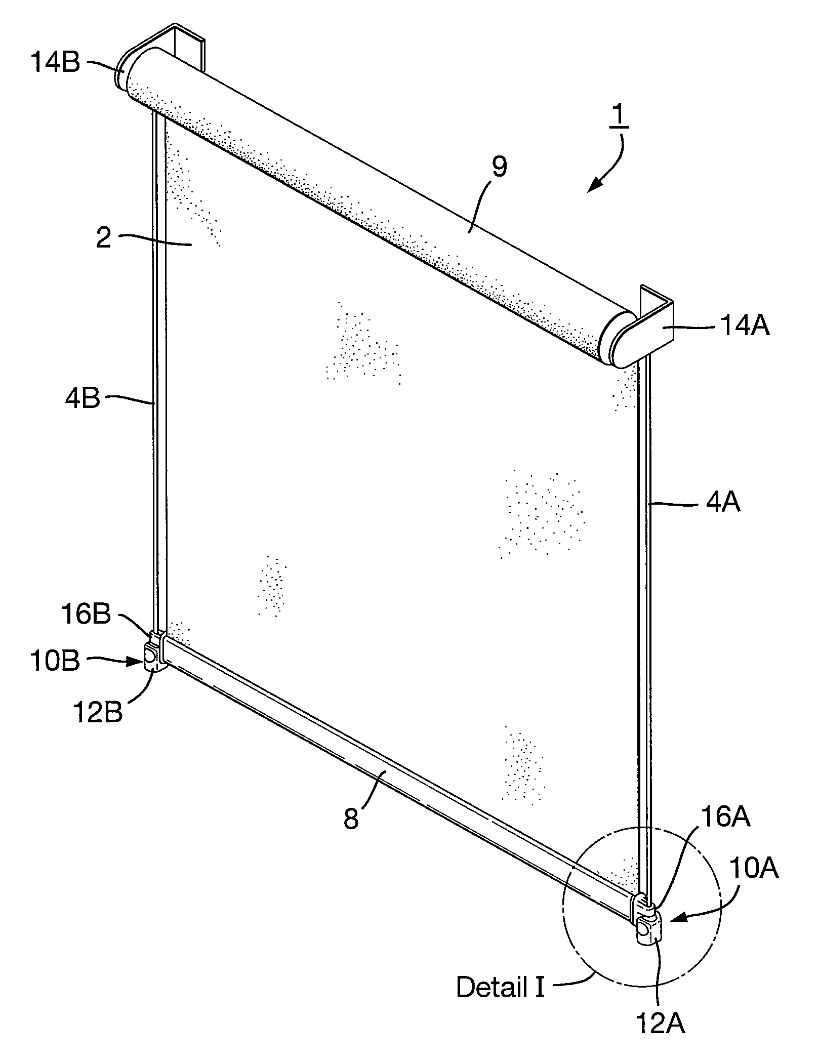
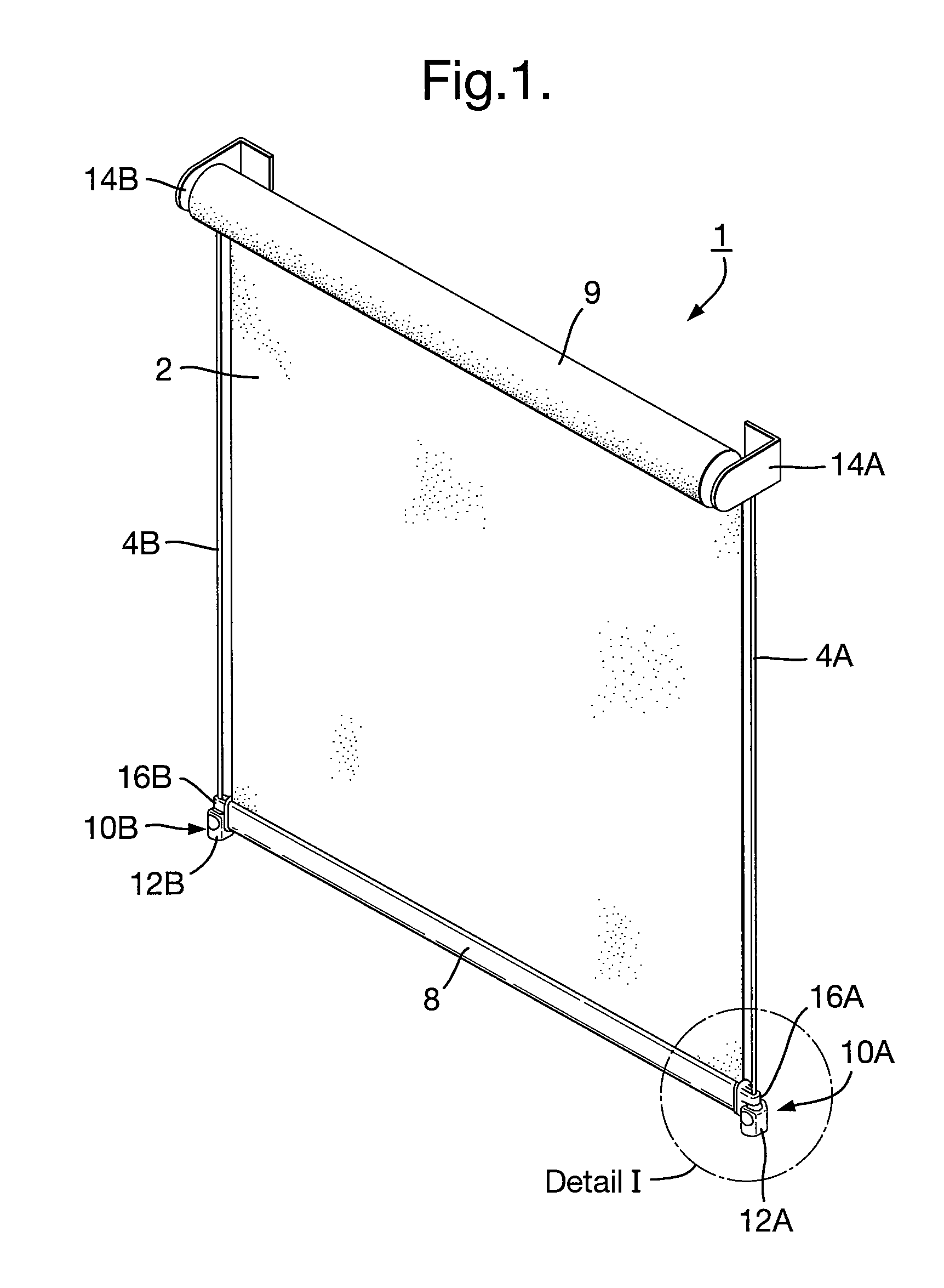
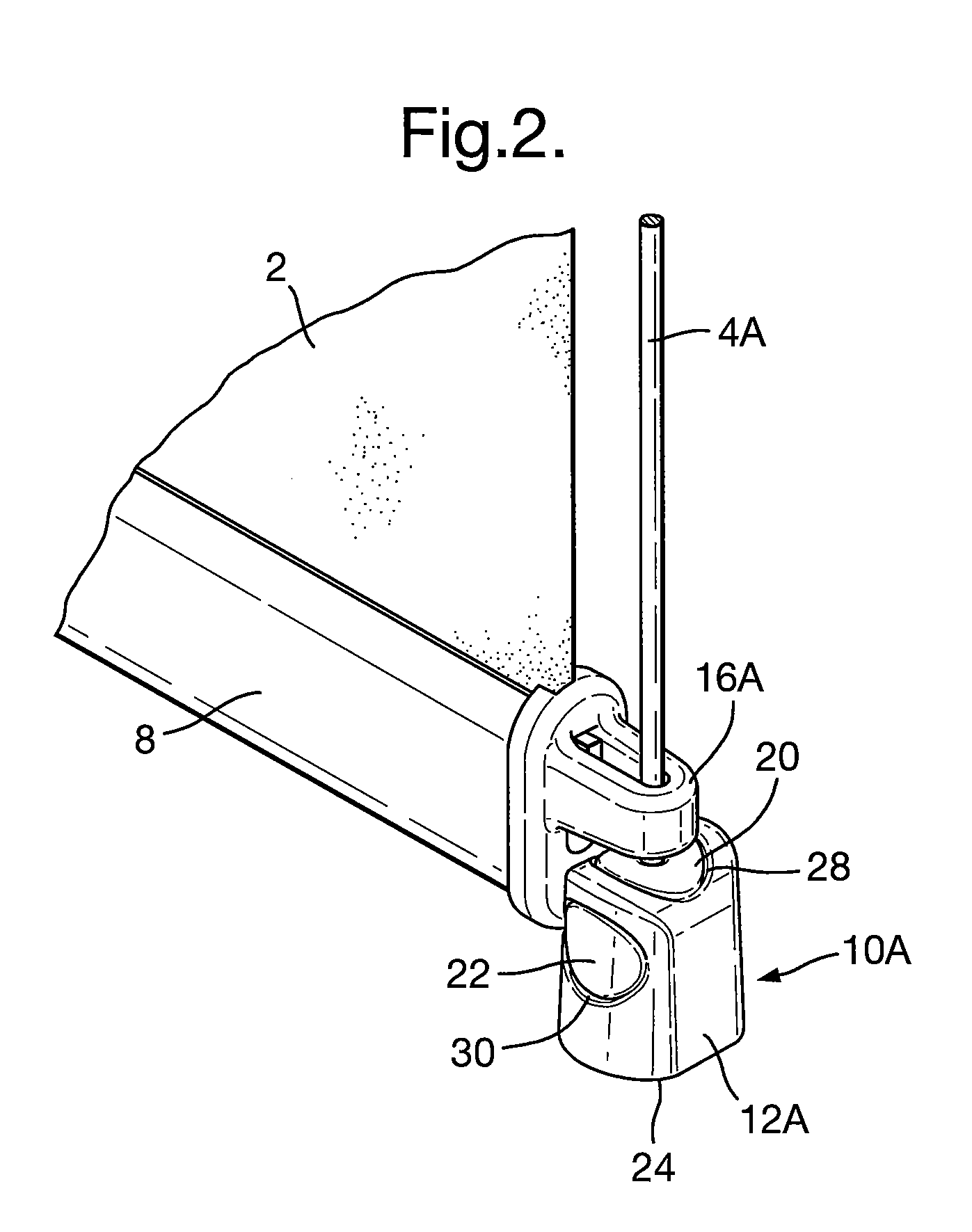
[0025]FIG. 1 shows an example of an architectural covering 1, suitable for covering for example a window in a wall or a ceiling (not shown but known to the skilled person). The architectural covering includes a rollable screen 2, a right-hand guide cable 4A and a left-hand guide cable 4B that extend in the vertical direction in this example, a roller 9, a bottom bar 8, a right-hand anchoring device 10A including a right-hand body 12A and a left-hand anchoring device 10B including a left-hand body 12B. The guide cables 4A and 4B are examples of an elongate guide element. Distinct parts of the architectural covering 1 that are similar are indicated by the same number followed by a distinct index letter, such as for example the right-hand guide cable 4A and the left-hand guide cable 4B. The roller 9 is rotatably supported by a right-hand bracket 14A and a left-hand bracket 14B. The right and left bracket 14A, 14B may optionally be part of a roller mounting frame (not shown but conventi...


PUM


Abstract

The invention provides an anchoring device for anchoring an elongate guide element of an architectural covering. The anchoring device includes a body having a rear surface. The body is suitable for attachment to a support structure with the rear surface in close contact with the support structure. The body includes a receiving cavity for receiving the elongate guide element, a first entrance to the receiving cavity and a second entrance to the receiving cavity. The receiving cavity can receive the elongate guide element selectively either through the first entrance, with the rear surface having a first orientation with respect to the elongate guide element, or through the second entrance, with the rear surface having a second orientation with respect to the elongate guide element, and wherein the second orientation is substantially different from the first orientation.

Description

CROSS REFERENCE TO RELATED APPLICATION[0001]This application claims priority to European Patent Application No. 07017189.7 filed on 3 Sep. 2007, and such application is hereby incorporated by reference as if fully disclosed herein.BACKGROUND OF THE INVENTION[0002]1. Field of the Invention[0003]The invention relates to a device for anchoring a rigid or flexible elongate guide element, such as a guide cable or rod, of an architectural covering, such as a roller blind, a roller screen, a pleated blind, a venetian blind, or a roman shade.[0004]2. Description of the Relevant Art[0005]Devices for anchoring elongate guide elements of architectural coverings are known from the prior art. For example, GB1007045 discloses a securing device for a guide cable of a venetian blind that can be attached to a vertical surface, for example a surface of a wall. As a further example, BE629561 discloses a device for anchoring a guide cable of a venetian blind which can be attached to a horizontal surfac...

Claims


Application Information

Patent Timeline
Patent Type & Authority Patents(United States)
IPC IPC(8): A47H3/00
CPCE06B9/327E06B9/58Y10T24/3967E06B2009/587Y10S248/911E06B2009/583
Inventor GARMYN, TOMAS M. A. H.
Owner HUNTER DOUGLAS IND BV
Why Eureka
Try Eureka