Decorative wall covering with improved interlock system

a technology of interlocking system and decorative wall covering, which is applied in the direction of roofs, coverings/linings, constructions, etc., can solve the problems of installation difficulty, installation difficulty, and installation difficulty, and achieve the effect of convenient and reliable installation

Active Publication Date: 2011-07-19
NOVIK INC
View PDF54 Cites 24 Cited by
  • Summary
  • Abstract
  • Description
  • Claims
  • Application Information

AI Technical Summary

Benefits of technology

[0005]It is an object of the present invention to provide a wall covering comprising thermoplastic wall or roof panels which have an interlock arrangement between overlapping upper end marginal edge regions of panels that is adapted for easier and more-reliable engagement during installation.
[0006]Another object is to provide a wall or roof panel as characterized above that facilitates proper positioning of a panel into overlying relation to a previously-installed panel.
[0007]A further object is to provide a panel of the above kind which effects positive interlocking engagement of an overlying panel onto a previously-mounted panel sufficient to support the weight of the panel during securement onto the wall surface. A related object is to provide such a panel interlock arrangement that is releasable to permit adjustable positioning of the panel during installation if necessary, and to accommodate expansion and contraction of the panels from temperature changes during usage.
[0009]A further object is to provide such a wall panel in which the upturned interlock rail across the rear of the panel facilitates water drainage and air circulation through the completed wall covering.
[0010]Still another object is to provide a wall or roof panel of such type which is relatively simple in construction and which lends itself to economical molding.

Problems solved by technology

Because the panels are relatively large, such as up to eight feet and more in length, they can be cumbersome to handle and install, particularly on vertical wall and steep roof surfaces.
Leakage problems between adjoining panels can also occur under these circumstances.
Due to the size of the panels it can be difficult for the installer to engage all of the fingers with the upturned rail, with any missed fingers causing an unsightly bowing of the overlying panel, which both detracts from its appearance of the finished wall covering and makes it more susceptible to water entering the juncture between the panels.
Even when the panel is properly positioned, it can be difficult for the installer to properly hold and maintain a panel and at the same time nail or screw it to the wall surface.
The upturned rail also can undesirably capture and retain water that might migrate between the panels, such as during severe weather conditions.

Method used


Image

  • Decorative wall covering with improved interlock system
  • Decorative wall covering with improved interlock system
  • Decorative wall covering with improved interlock system

Examples


Embodiment Construction

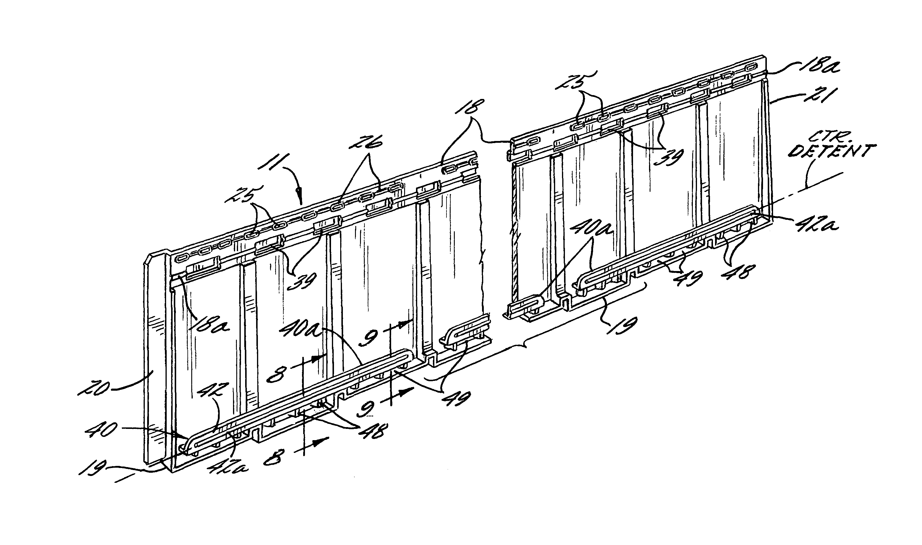
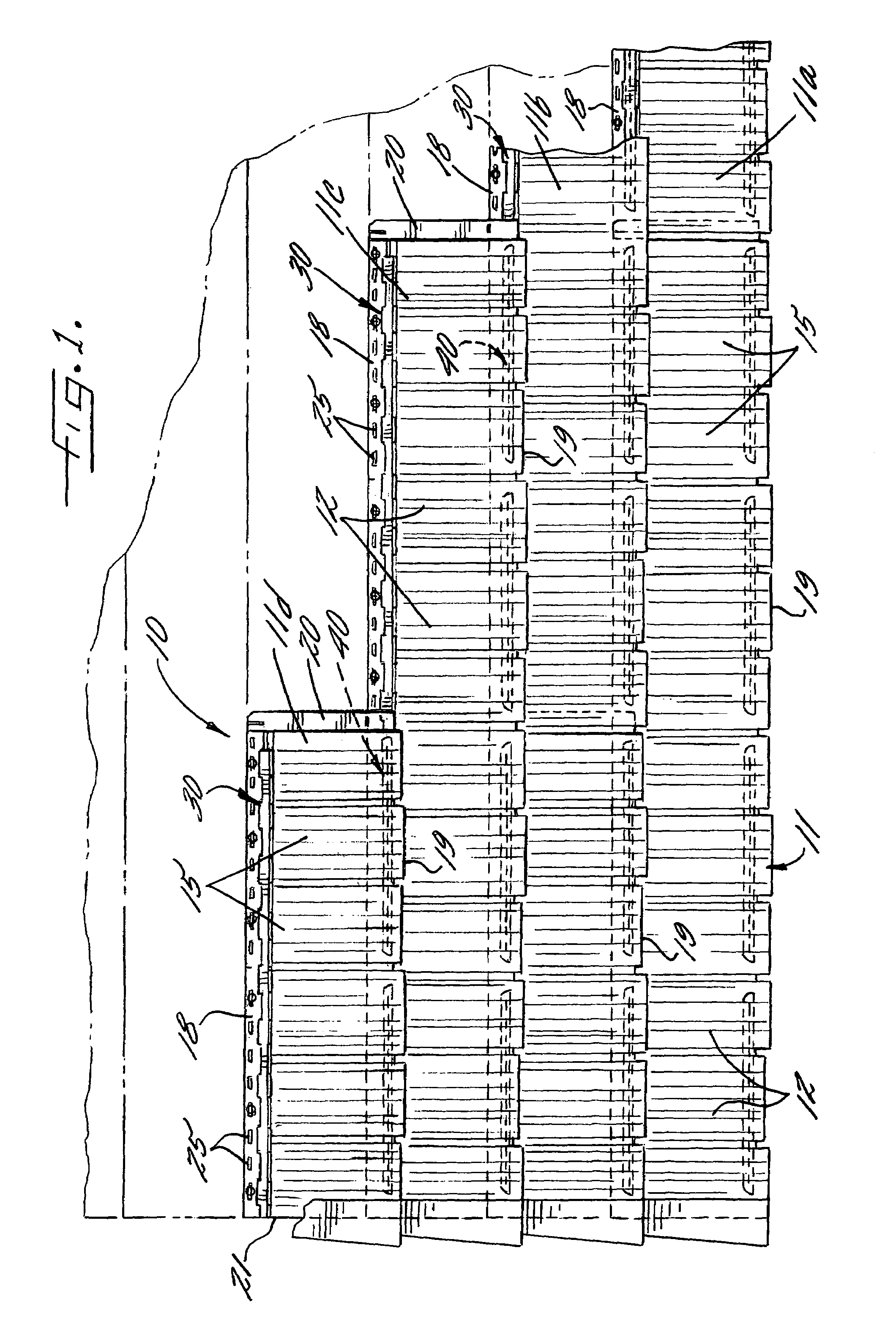
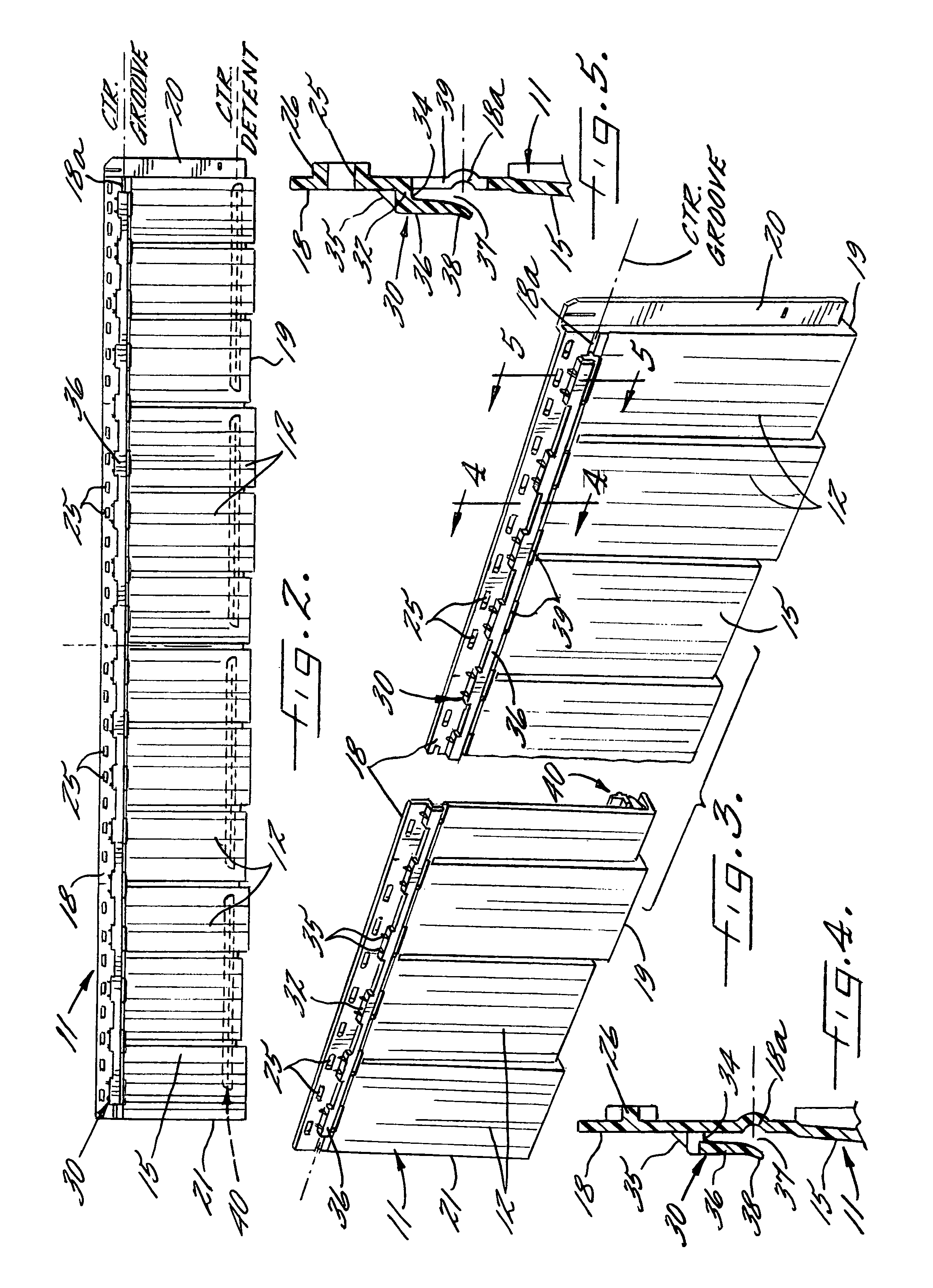
[0022]Referring now more particularly to FIG. 1 of the drawings, there is shown an illustrative wall covering 10 comprising a plurality of plastic molded panels 11 in accordance with the present invention. The general type of panel employed in the instant invention is described in commonly assigned U.S. Pat. Nos. 5,347,784 and 5,537,792, the disclosures of which are incorporated herein by reference. As shown in FIG. 1, the panels 11 each are formed with simulated building elements. In this instance, the panels 11 are formed with simulated cedar shake shingles 12 of irregular width and length which are disposed in a single row substantially along the length of the panel.

[0023]The simulated shake shingles 12 in this case each have a front face 15 (FIG. 3) extending downwardly and outwardly at a slight taper to a wall or support surface 17 upon which the panel is mounted, and the front face 15 is molded with grooves which simulate the grain of the simulated shake 12. It will be underst...


PUM


Abstract

A roof or wall covering comprising a plurality of horizontal courses of molded plastic panels each formed with a single row of simulated shake shingles. The panels have a continuous upper interlock flange that facilitates inner-engagement of the panels of overlying courses without cumbersome handling of numerous small interlock fingers which can be missed during installation. Cooperating detents are provided between the overlying lower and upper marginal edge regions which facilitate proper positioning of the panels and which support the weight of the panel during securement to a wall surface. A bottom interlock flange is supported transversely across a rear side of the panel by vertically-spaced support plates which facilitate both liquid drainage and air circulation through the installed wall covering. In the preferred embodiment, the panels in alternate courses are identically formed with different shake patterns for enhancing the natural appearance of the wall covering.

Description

FIELD OF THE INVENTION[0001]The present invention relates generally to roof and wall coverings which are primarily intended for outdoor usage, and more particularly, to roof and wall coverings comprised of relatively large panels which each are molded or otherwise formed with decorative patterns characteristic of conventional roofing and siding materials, such as shake shingles, tile, brick or the like.BACKGROUND OF THE INVENTION[0002]Various synthetic roof and wall coverings are known, such as those formed of elongated thermoplastic panels that are nailed or screwed to a wall or roof support surface in horizontal courses or rows in partially overlapping relation to each other so as to provide a substantially water resistant, protective layer over the support surface. Such panels, which usually are identically molded, are commonly formed with a plurality of rows of simulated building elements, such as shake shingles. Because the panels are relatively large, such as up to eight feet ...

Claims


Application Information

Patent Timeline
Patent Type & Authority Patents(United States)
IPC IPC(8): E04D1/00E04F17/00
CPCE04D1/265E04D1/2918E04D1/2921E04F13/0858
Inventor TRABUE, ROBERTSCHWARZ, STEFAN
Owner NOVIK INC
Why Eureka
Try Eureka