

Feeding structure for sliding structural body
a technology for sliding structural bodies and feeding structures, which is applied in the direction of cage suspension devices, furniture parts, machine supports, etc., can solve the problems of difficult to absorb a redundant length of wire harnesses, restrict the degree of freedom of arranging other auxiliary devices, and take a lot of labor, so as to reduce the occupied space, thin structure, and compact feeding structure
- Summary
- Abstract
- Description
- Claims
- Application Information
AI Technical Summary
Benefits of technology
Problems solved by technology
Method used
Image

Examples
Embodiment Construction
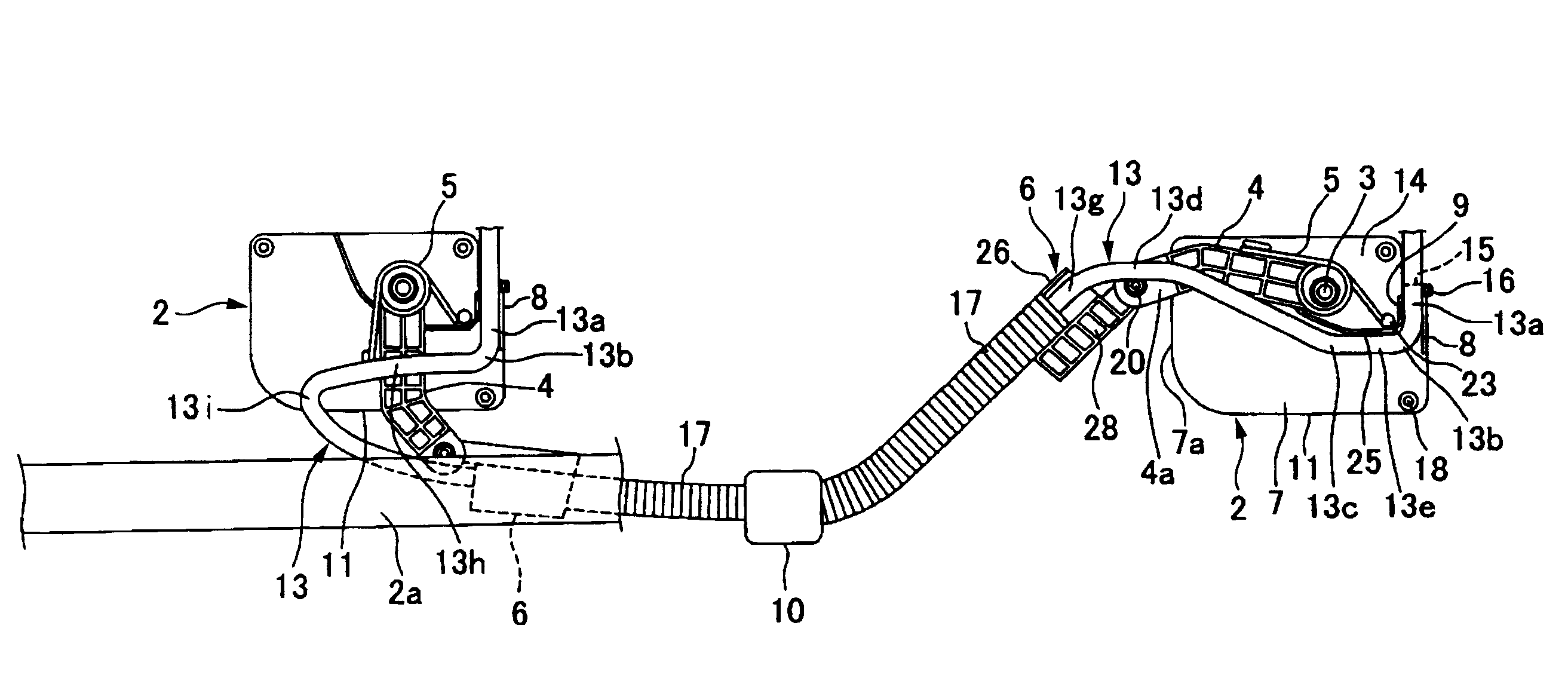
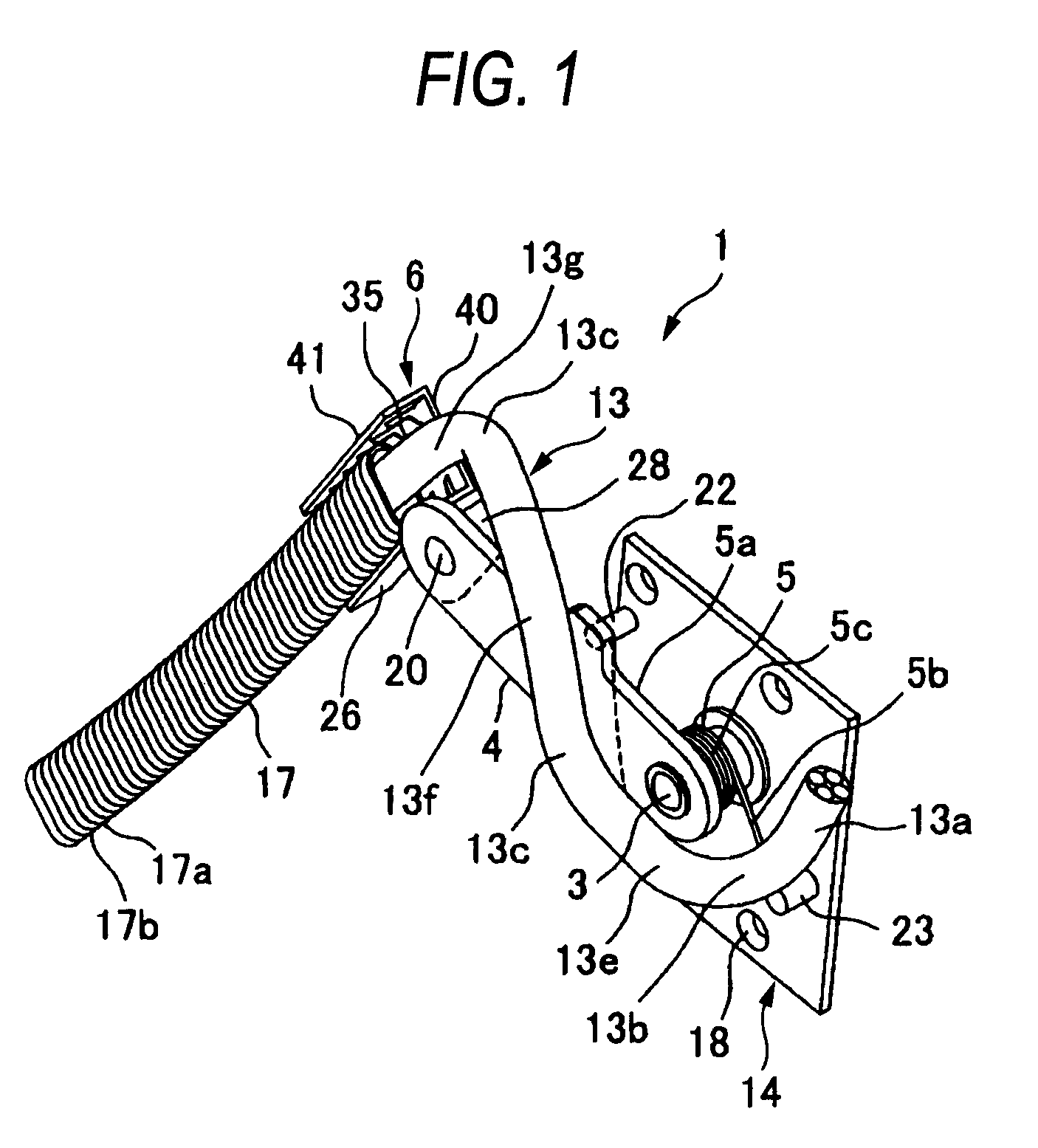
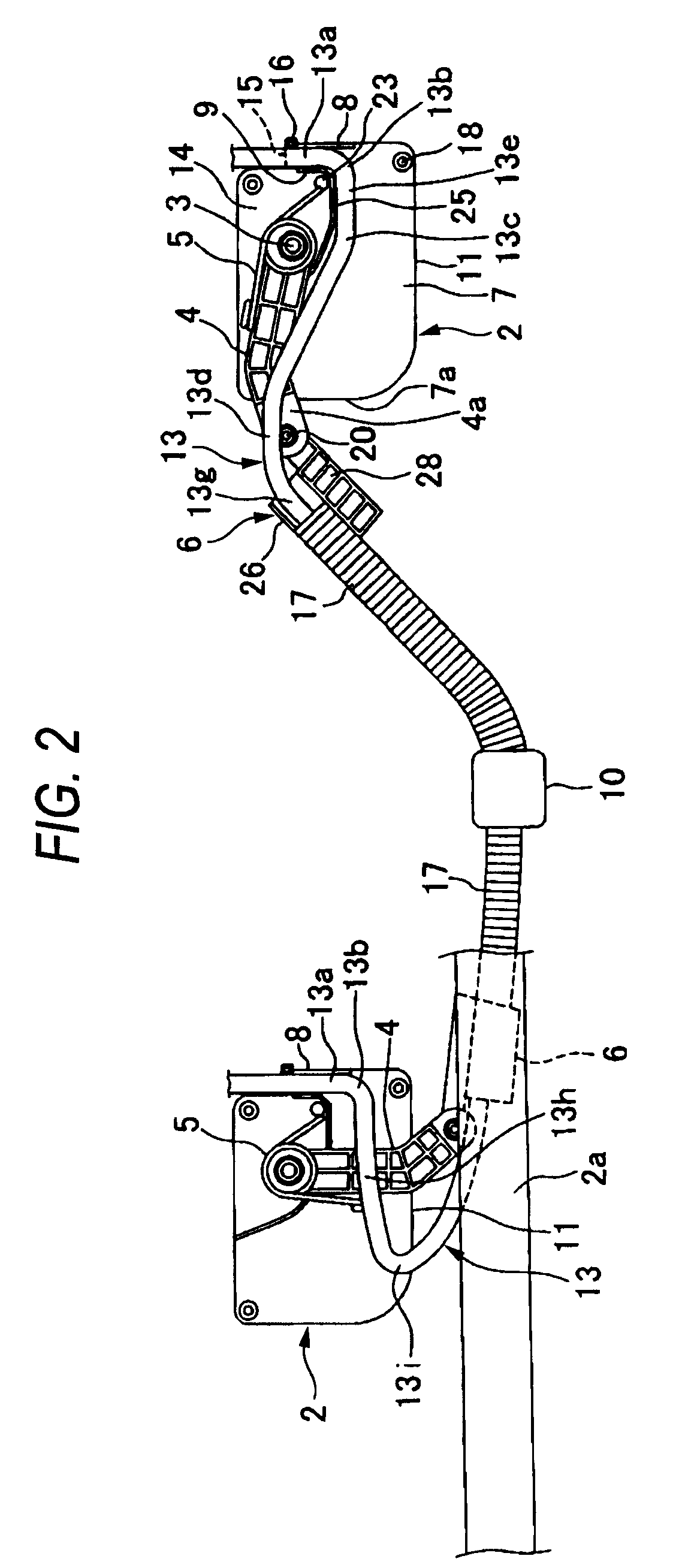
[0039]FIGS. 1 to 3 are views showing an embodiment of the feeding structure for a sliding structural body of the present invention. In FIG. 2, for the convenience of explanations, operation states of the feeding unit at the time of opening and closing the sliding structural body are respectively shown by solid lines.
[0040]As shown in FIG. 1, this feeding structure includes: a protector base 2 (shown in FIG. 2) made of synthetic resin vertically (longitudinally) mounted on a slide door (a sliding structural body) of an automobile; one link arm 4 made of synthetic resin, the shaft portion 3 on the base portion side of the link arm being pivotally supported by the protector base 2; a torsion coil spring (an elastic member) 5 made of metal for pushing the link arm 4 upward; a harness holder 6 made of synthetic resin pivotally connected to a forward end portion of the link arm 4; and a wire harness 13 which is laid from the forward end side of the protector base 2 to the harness holder 6...
PUM
 Abstract
Description
Claims
Application Information