
Method for imaging the earth's subsurface using passive seismic sensing

a technology of seismic sensing and earth's subsurface, which is applied in the field of seismic imaging of the earth's subsurface, can solve the problems of unsafe or impracticable use of seismic sources, ambiguous pstt, and inability to use conventional controlled source seismic techniques

Inactive Publication Date: 2011-07-26
MICROSEISMIC
View PDF19 Cites 12 Cited by
  • Summary
  • Abstract
  • Description
  • Claims
  • Application Information

AI Technical Summary

Problems solved by technology

In some cases it may be undesirable to use conventional controlled source seismic techniques for evaluating the Earth's subsurface, for example, if a particular area is environmentally sensitive so as to make access and use of seismic sources unsafe or impracticable.
While effective, PSTT may provide ambiguous results or may require very long signal recording time to generate unique results.

Method used


Image

  • Method for imaging the earth's subsurface using passive seismic sensing
  • Method for imaging the earth's subsurface using passive seismic sensing
  • Method for imaging the earth's subsurface using passive seismic sensing

Examples


Embodiment Construction

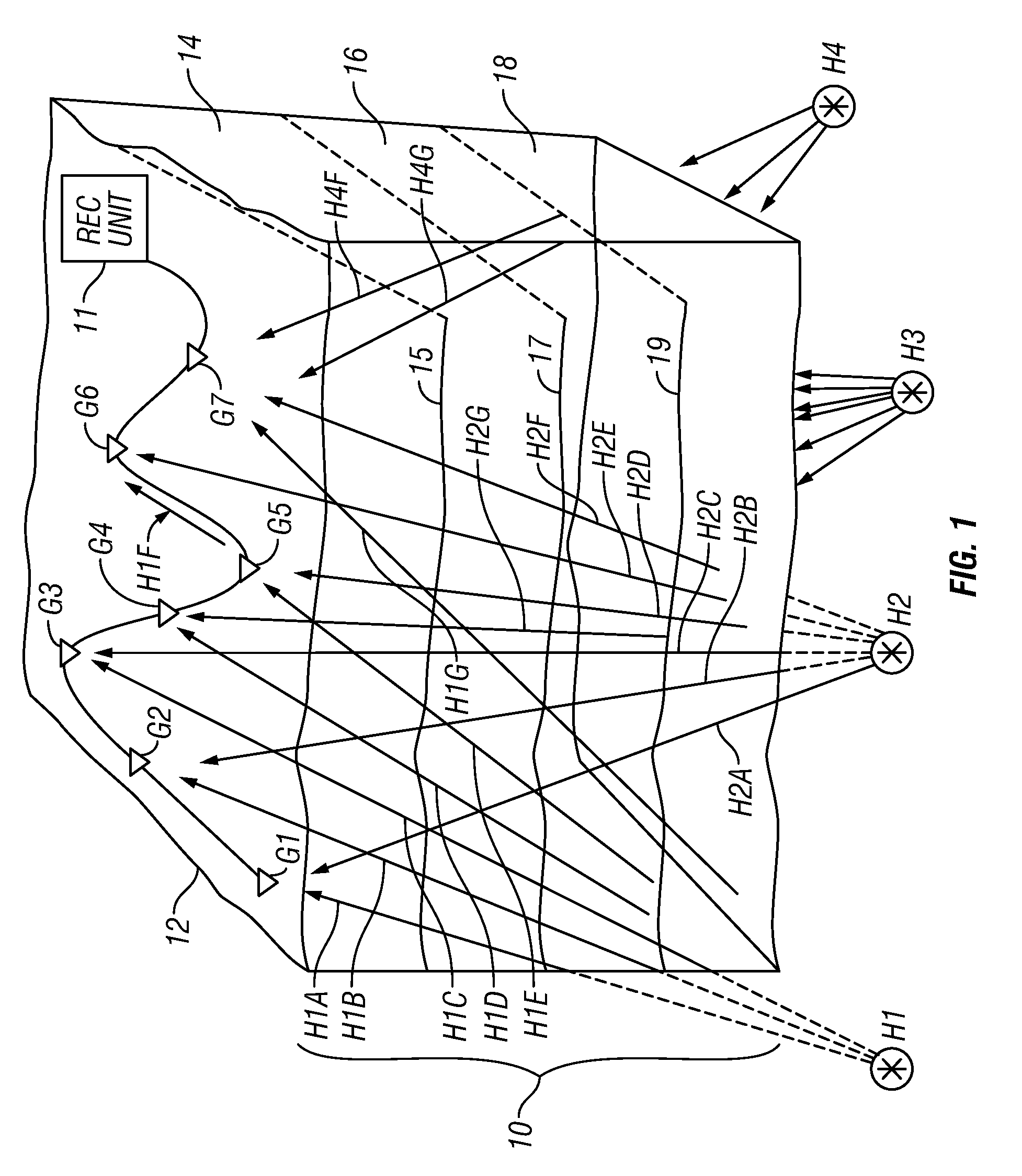
[0014]FIG. 1 shows an array of seismic sensors, individually identified as G1 through G7, disposed at selected positions near or on the surface 12 of the Earth above a volume 10 of the Earth's subsurface to be imaged using passive seismic signals. The subsurface volume 10 may include a plurality of different formations, examples of which are shown at 14, 16 and 18, each having distinct seismic properties (e.g., acoustic impedance). A boundary 15, 17, and 19 may represent the surface that separates two adjacent formations 14, 16 and 18, respectively. The seismic sensors G1 through G7 may be one- or three-component particle motion sensors, such as geophones, accelerometers or any similar

[0015]During recording of the signals produced by each of the seismic sensors G1-G7, various microearthquakes or other seismic events, shown at their possible points or origin (“hypocenters”) H1, H2, H3 and H4, may occur in the subsurface in or below the volume 10. The seismic events each produce seism...


PUM


Abstract

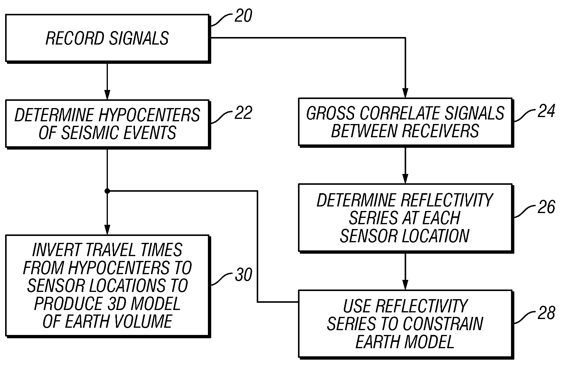
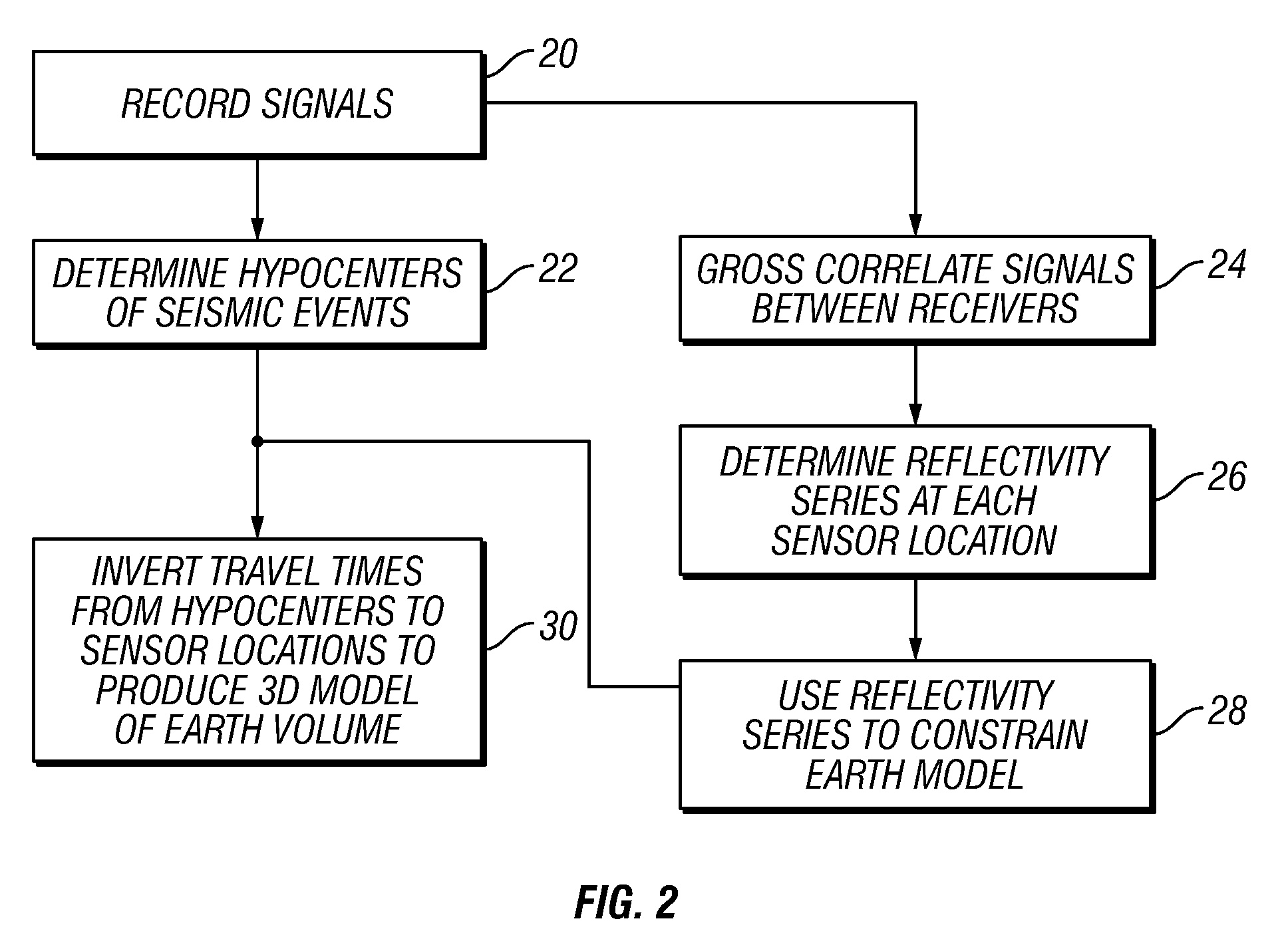
A method of imaging the Earth's subsurface using passive seismic emissions includes detecting seismic signals originating from within the Earth's subsurface over a selected time period using an array of seismic sensors deployed proximate the Earth's surface. Hypocenters of seismic events in the subsurface are determined from the detected signals. Seismic signals detected at selected ones of the seismic sensors are cross-correlated to signals detected at other selected ones of the seismic sensors. The cross-correlated signals are processed to obtain a reflectivity series at a geodetic position of the selected one of the seismic sensors. A spatial distribution of at least one seismic property in the subsurface is determined using the determined hypocenters and the reflectivity series.

Description

CROSS-REFERENCE TO RELATED APPLICATIONS[0001]Not applicable.STATEMENT REGARDING FEDERALLY SPONSORED RESEARCH OR DEVELOPMENT[0002]Not applicable.BACKGROUND OF THE INVENTION[0003]1. Field of the Invention[0004]The invention relates generally to the field of seismic imaging of the Earth's subsurface. More specifically, the invention relates to imaging of the Earth's subsurface using passive seismic sensing techniques.[0005]2. Background Art[0006]Passive seismic emission sensing techniques include detecting seismic signals from within the Earth's subsurface. As contrasted with conventional controlled source seismic exploration techniques (wherein a seismic source is actuated near the Earth's surface), in passive seismic sensing, the seismic signals are generated by seismic events taking place within the Earth's subsurface. The subsurface seismic events may be naturally-occurring or may be induced by man-made activities. The seismic signals are detected by an array of seismic sensors pos...

Claims


Application Information

Patent Timeline
Patent Type & Authority Patents(United States)
IPC IPC(8): G01V1/00
CPCG01V1/366G01V1/288G01V2210/123
Inventor DUNCAN, PETER M.LAKINGS, JAMES D
Owner MICROSEISMIC
Learn More