Folding tool

a folding tool and tool body technology, applied in the direction of thrusting weapons, white arms/cold weapons, weapons, etc., can solve the problems of extreme danger, insufficient strength of arm shape, and insufficient pressure on the blade body to clos

Inactive Publication Date: 2011-08-02
MENTOR GROUP
View PDF3 Cites 16 Cited by
  • Summary
  • Abstract
  • Description
  • Claims
  • Application Information

AI Technical Summary

Benefits of technology

[0021]The present invention is constituted as described above, and has the effect to enable releasing the lock in a safe position without holding the main body and a handle when folding and without positioning fingers in the line of rotation of the blade end portion of the blade body as was conventional.
[0022]Also, when a strong pushing pressure is applied from the rear of the main body, a pulling pressure is produced in the convex portion of the base end of the arm-shaped plate of the side plate. With conventionally produced side plates, the arm-shaped plate is provided at the ventral portion, and the end portion ventral locking portion of the blade body and the engaged liner lock apply a pushing pressure on the arm, decreasing the lock functionality of the arm; however, the present invention has the effect of retaining the strength of the lock functionality of the arm and of furthermore enabling the blade body to be opened smoothly like conventional liner locks.
[0023]As with knifes, the present invention can safely store keys, saws, and various types of tools, releasing them for use according to need.

Problems solved by technology

When closing the blade body, the blade end portion of the blade body is in the line of rotation; and when releasing the lock, the arm-shaped plate has to be pushed with one hand to release, and the blade body has to be closed with the other hand, which is extremely dangerous.
There are also locking methods whereby a locking portion is attached toward the back of the knife such that fingers are not positioned in the line of rotation of the blade end portion of the blade body when closing the blade body; however, the strength of the arm shape is considered inadequate for the pushing pressure for closing the blade body.

Method used


Image

  • Folding tool
  • Folding tool
  • Folding tool

Examples


Embodiment Construction

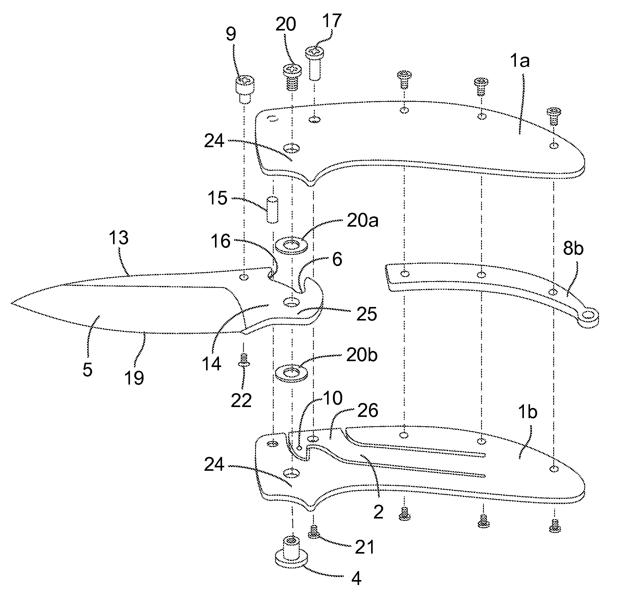
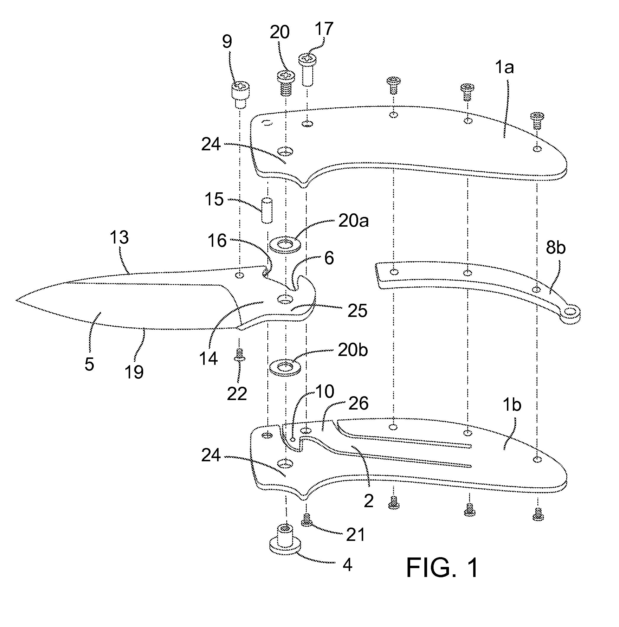
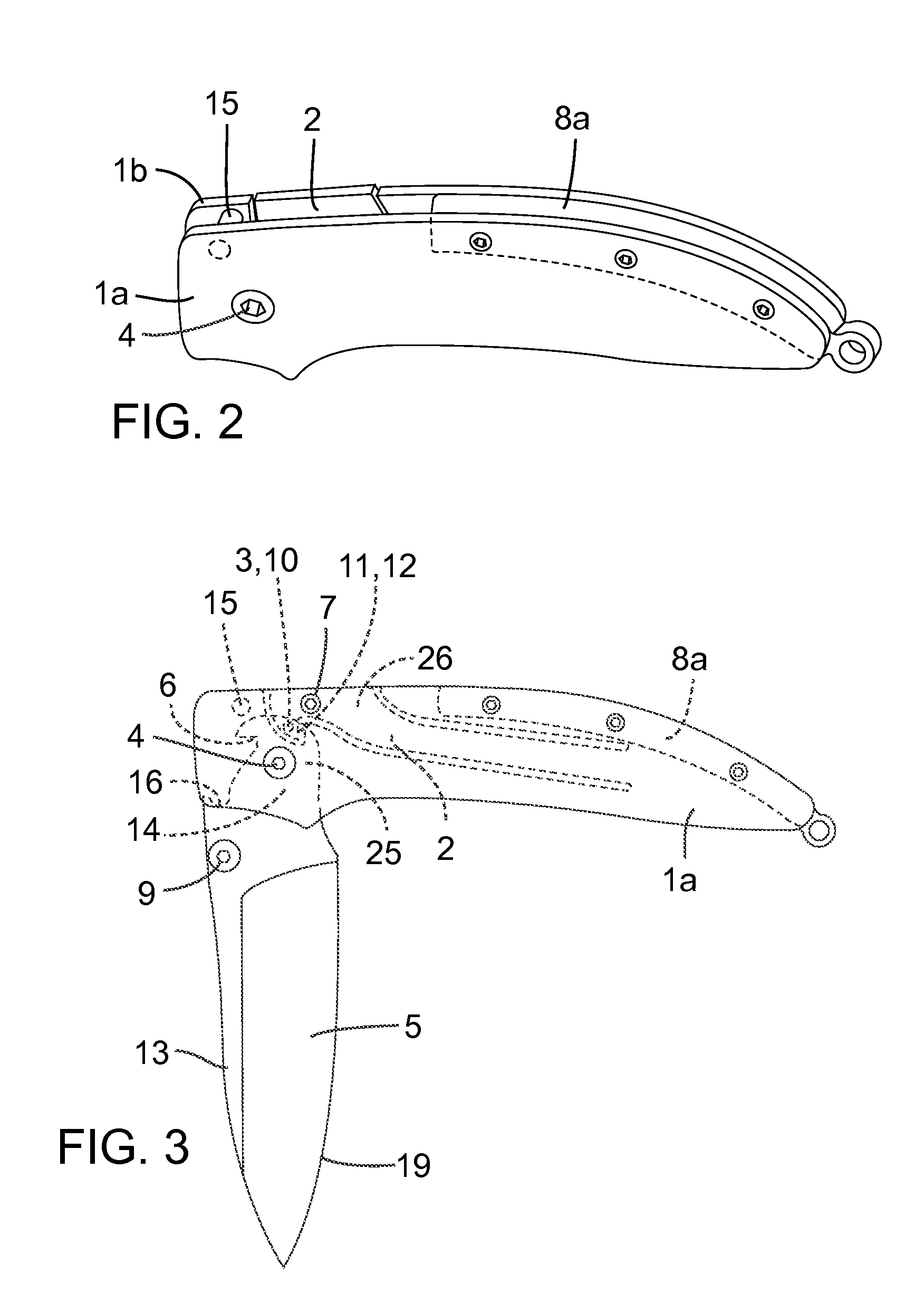
[0020]Conventionally, there have been a number of proposals for improved technologies. While safely lockable mechanisms have been proposed, fingers are required to be placed in the line of rotation of the blade end portion when being closed, which is unfavorable from the viewpoint of safety and lacks adequate strength; consequently, such proposals are inadequate from the viewpoint of safety. It is an aim of the present invention to solve these shortcomings. These sorts of problems are not limited to knives, but are common to key holders, small tool holders for screwdrivers, saws, and the like.

[0021]The present invention is constituted as described above, and has the effect to enable releasing the lock in a safe position without holding the main body and a handle when folding and without positioning fingers in the line of rotation of the blade end portion of the blade body as was conventional.

[0022]Also, when a strong pushing pressure is applied from the rear of the main body, a pull...


PUM


Abstract

The folding tool has one side-plate (1a) and the other side-plate (1b). A part of the rear side of the other side-plate (1b) or an arm-like plate (2) attached as a separate body is used as an inwardly pressing member, and a projection (3) is provided at the head of the arm-like plate (2). The base end of the body (5) having at its end a rear recess (6) is foldably pivotally attached by means of a support shaft (4) to the base ends of both the one side-plate and the other side-plate. The projection (3) and the recess (6) of the body (5) are engaged with and locked to each other.

Description

TECHNICAL FIELD[0001]The present invention is a folding device having a mechanism to safely and securely fasten as well as easily release an opening and closing lock provided in a pocketknife or the like.BACKGROUND OF THE INVENTION[0002]In a conventional lockable pocketknife, a back spacer is rotatably attached through a spindle to the back between a pair of side plates, a blade body base end is foldably attached through a spindle to the tip portion between both side plates, and a convex portion of the end of the back spacer and an end portion dorsal concave portion engage. When closing the open blade body, the tip had to be held with the fingers of one hand while closing with the other hand in order to release the lock of the portion at which the convex portion of the end of the back spacer and the end portion dorsal concave portion of the blade body engage.[0003]Additionally, a pocket knife is formed such that one of its pair of side plates is made into a long arm-shaped spring an...

Claims


Application Information

Patent Timeline
Patent Type & Authority Patents(United States)
IPC IPC(8): B26B1/04
CPCB26B1/044B26B1/046
Inventor NAKAMURA, SEIICHI
Owner MENTOR GROUP
Why Eureka
Try Eureka