
Deployable structures and methods for assembling same

a technology for deploying structures and structures, applied in the direction of buildings, buildings, constructions, etc., can solve the problems of lack of structural members in the central columnar space, lack of head room via an open,

Inactive Publication Date: 2011-08-02
JACKSON HARRISON JOSHUA
View PDF51 Cites 9 Cited by
  • Summary
  • Abstract
  • Description
  • Claims
  • Application Information

AI Technical Summary

Benefits of technology

"The present invention is a deployable structure that includes a structural mechanism with a plurality of structural members, couplings, and tension lines. The couplings interconnect the structural members and the tension lines are interconnected within the structural mechanism. The structural members can be made of materials such as plastic, PVC tubing, wood, or graphite composite. The couplings can have elastic cords secured to them and can stop the ends of the structural members from traveling completely through the coupling. The tension lines can be secured to the couplings and are an integral part of the outer covering of the structure. The deployable structure can be a tent or a container and can also have tie lines and a method for assembling it. The technical effects of the invention include a compact and easily deployable structure that can be easily connected and disconnected, and a method for assembling it."

Problems solved by technology

However, one drawback in structures of this type is the lack of sufficient head room via an open, central columnar space devoid of any structural members.

Method used


Image

  • Deployable structures and methods for assembling same
  • Deployable structures and methods for assembling same
  • Deployable structures and methods for assembling same

Examples


Embodiment Construction

The foregoing is to be construed as only being an illustrative embodiment of this invention. Persons skilled in the art can easily conceive of alternative arrangements providing functionality similar to this embodiment without any deviation from the fundamental principles or the scope of this invention.

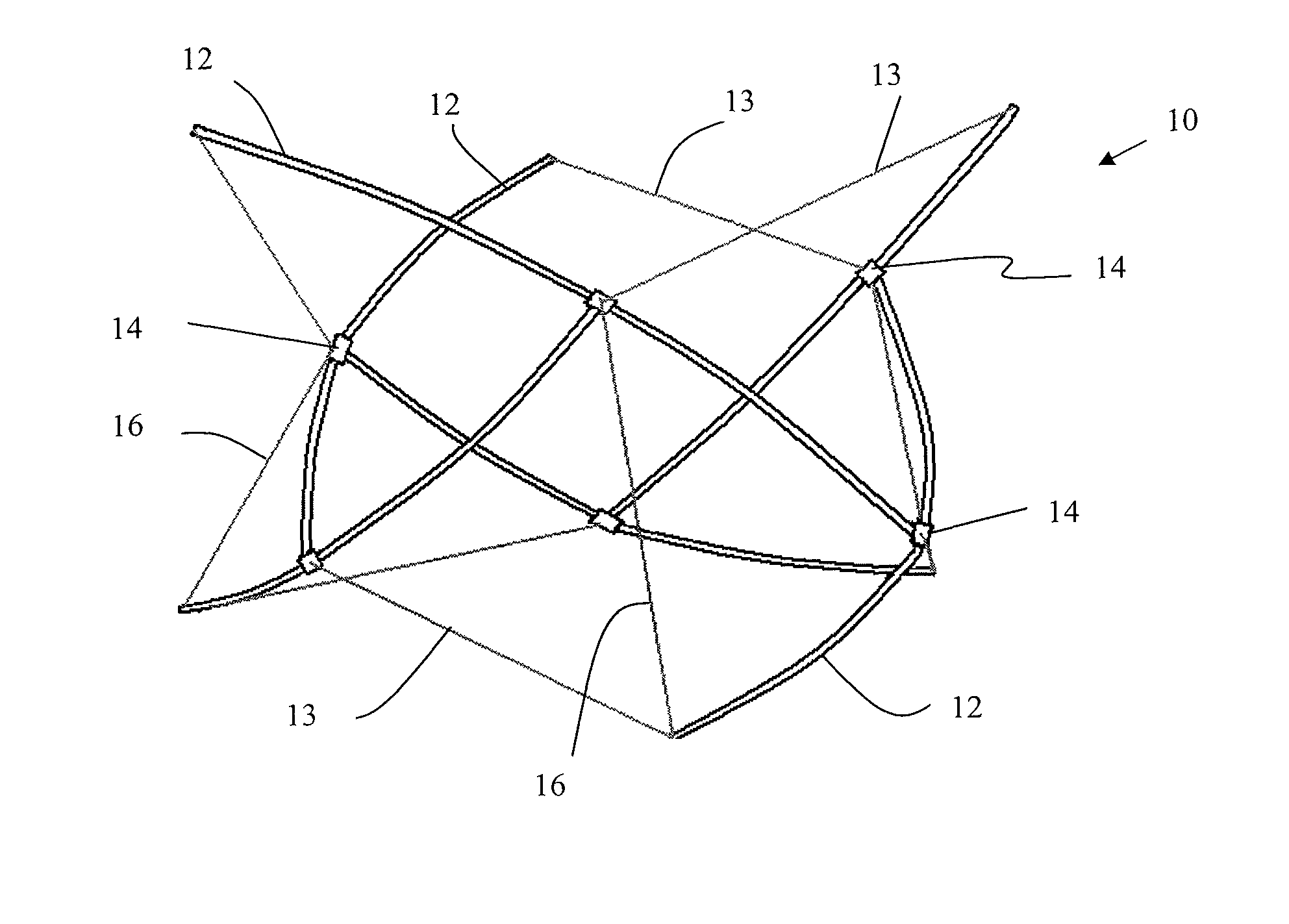
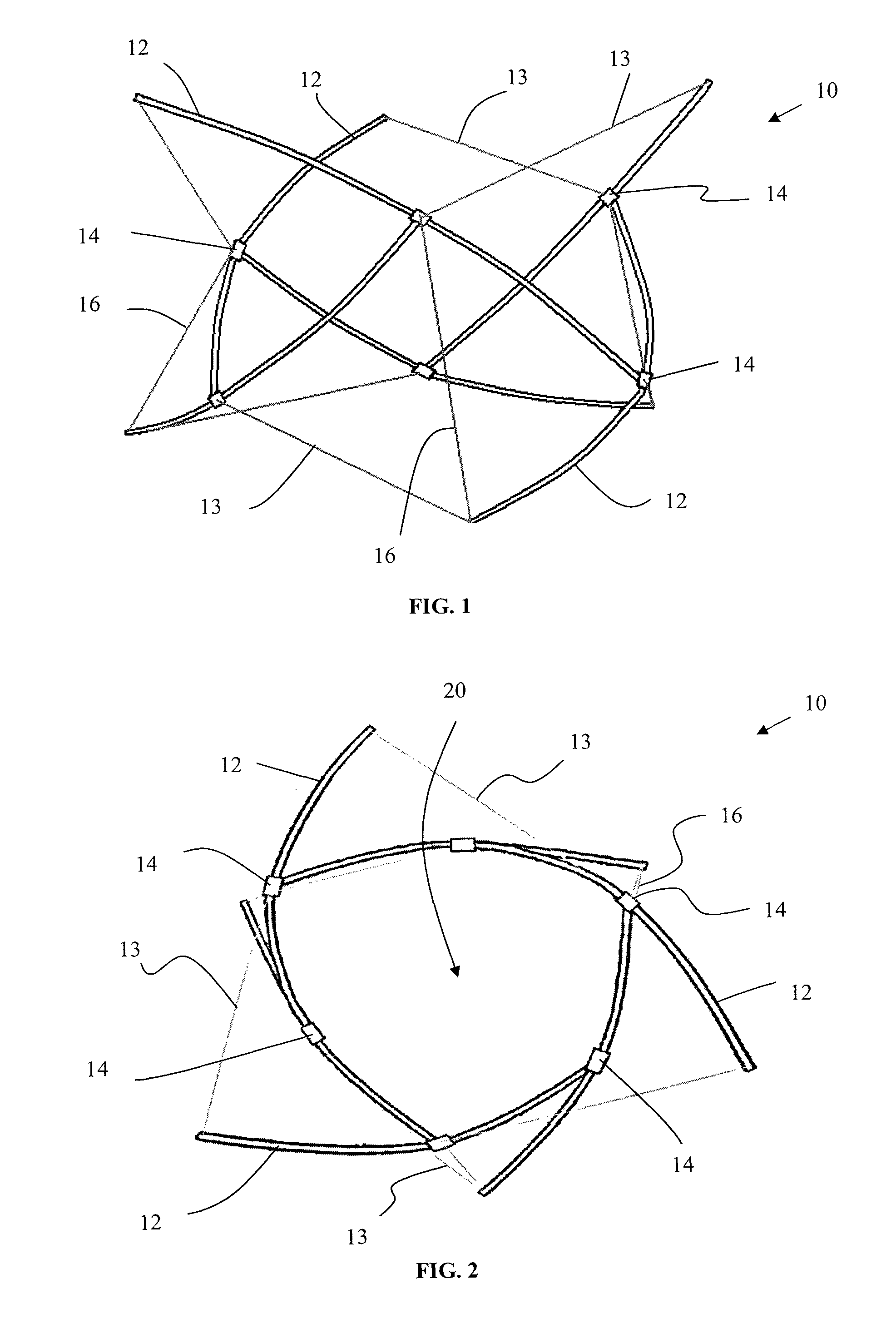
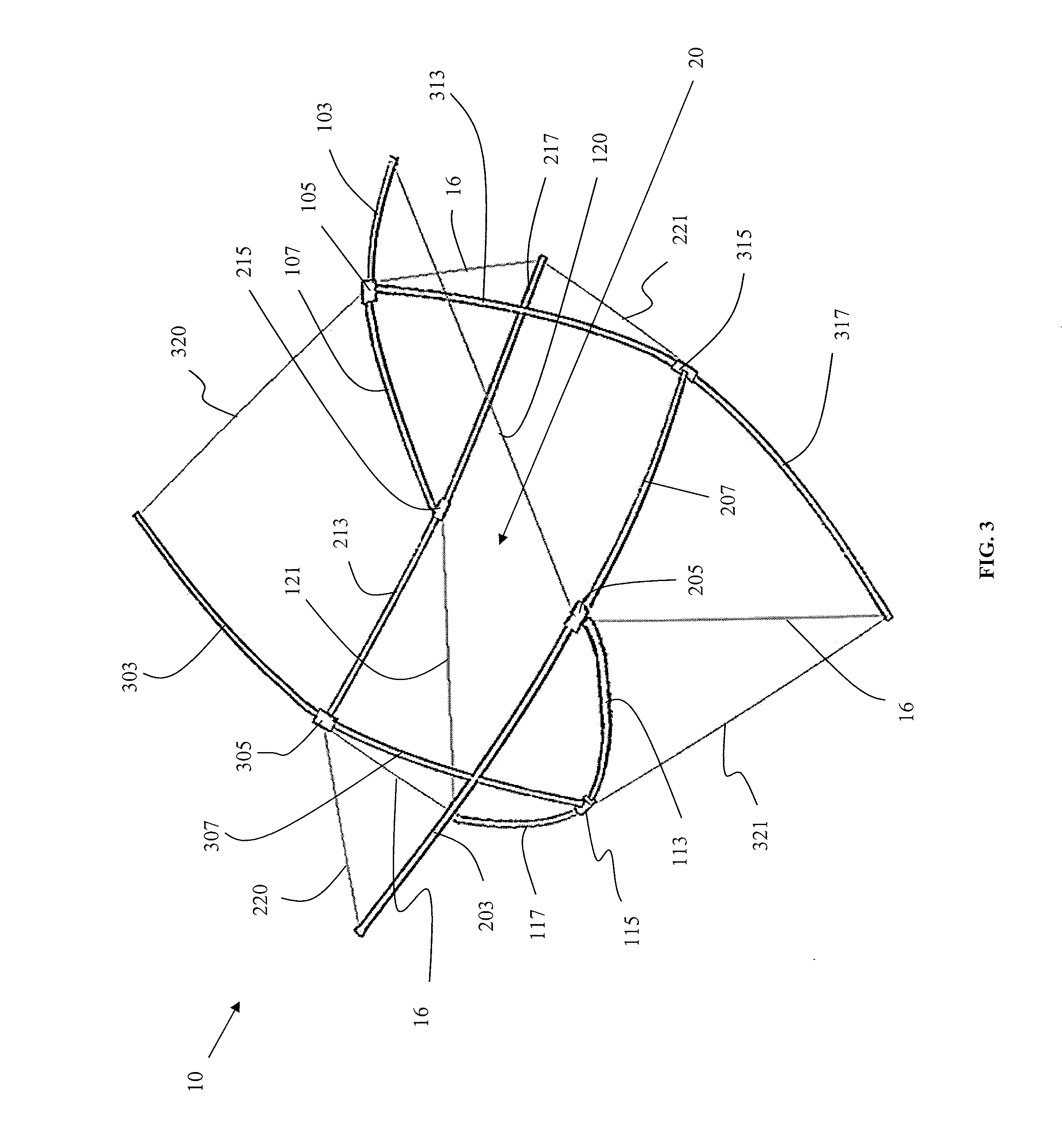
Referring to FIG. 1, a preferred embodiment of a deployable structure 10 according to the present invention comprises a plurality of structural members 12 interconnected via a plurality of tension lines 13, couplings 14 and tie lines 16. Deployable structure 10 is a collapsible, unitary design structure ideal for tents, but may also be scaled into smaller versions suitable for, but not limited to, clothes racks, hampers, toys, etc. Preferably, as shown in FIGS. 1-3, deployable structure 10 defines a central columnar space 20 in which no structural members 12, tension lines 13, couplings 14 or tie lines 16 are disposed. Rigidity and structural support of deployable structure 10 is deri...


PUM


Abstract

Deployable structures and methods for assembling the same including a structural mechanism defining a columnar space comprising a plurality of structural members, a plurality of couplings and a plurality of tension lines, wherein each of the couplings interconnects three of the structural members and each of the tension lines interconnects one of the couplings and one of the structural members. Each of the tension lines interconnects one of the couplings and an end of one of the structural members not interconnected with one of the couplings. A columnar space, devoid of any structural members, is centrally located within the structural mechanism. Each of the couplings interconnects two of three structural members such that they are substantially aligned along their respective longitudinal axes and the third of the three structural members is interconnected such that its longitudinal axis is substantially perpendicular to the longitudinal axes of the other two structural members.

Description

BACKGROUND OF THE INVENTION1. Field of the InventionThe present invention relates to deployable structures which include a structural mechanism which is movable for deployment of the structure. The deployable structures of the present invention may be used as structures in a wide range of applications ranging from small structures to large ones. They are particularly, but not exclusively, applicable as frames for tent-like structures.2. Description of the Related ArtPortable enclosures, such as tents, have been used as blinds and shelters for centuries. The structure and appearance of such enclosures vary greatly.More recently, easily portable, lightweight, durable and affordable enclosures have become a desirable accessory for many outdoor recreational activities, including camping and hunting. The widespread availability of modern lightweight structures and fabrics has resulted in the proliferation of literally hundreds of new designs for portable enclosures. Among the many popula...

Claims


Application Information

Patent Timeline
Patent Type & Authority Patents(United States)
IPC IPC(8): E04H15/44E04B1/32
CPCE04H15/001E04H15/44Y10S135/905
Inventor JACKSON, HARRISON JOSHUA
Owner JACKSON HARRISON JOSHUA
Learn More