Airbag system

US7988183B1Inactive Publication Date: 2011-08-02HONDA MOTOR CO LTD +1

Image

  • Airbag system
  • Airbag system
  • Airbag system

Examples


first embodiment

[0040]the present invention will be described below based on FIGS. 1 to 9B.

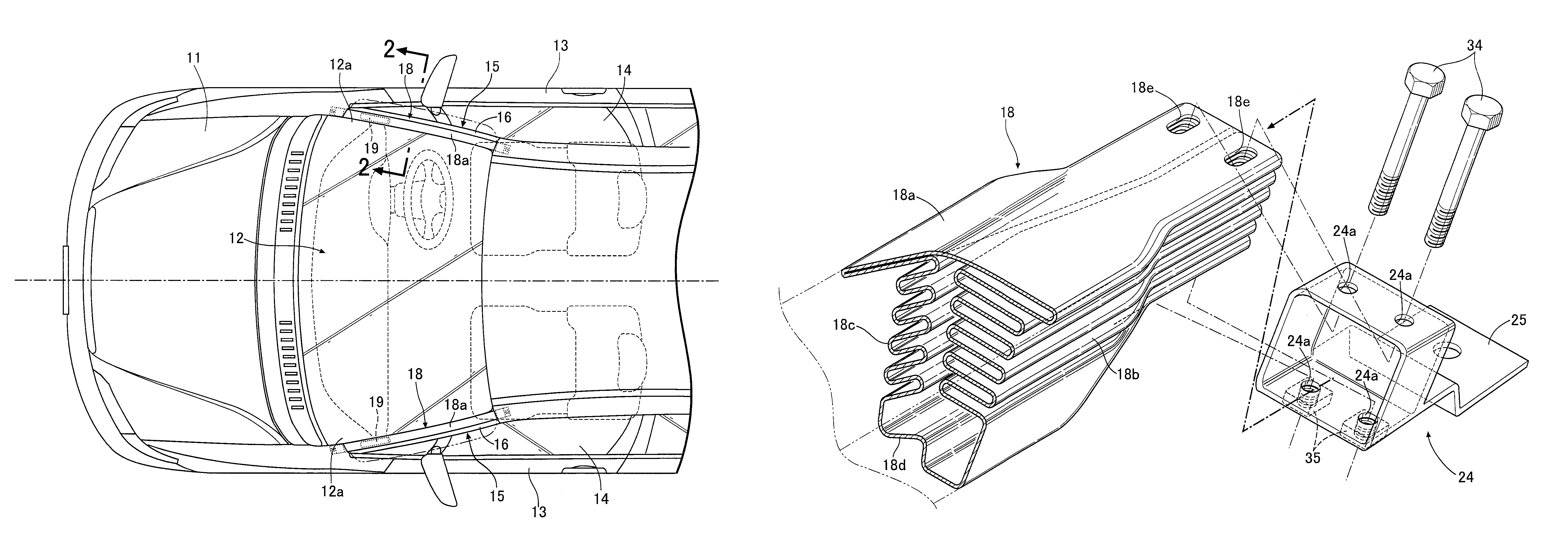
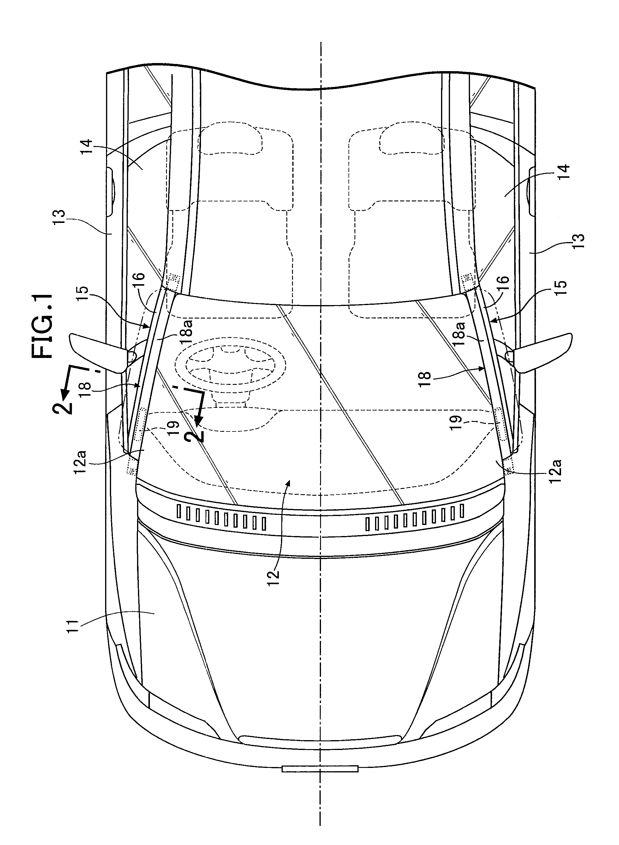
[0041]As shown in FIG. 1, an automobile has a front windshield 12 in the rear of a hood 11, and front pillars 15, 15 are arranged in a way that the front pillars 15, 15 are interposed between left and right edge portions 12a, 12a of the front windshield 12 and door glasses 14, 14 of front doors 13, 13, respectively.

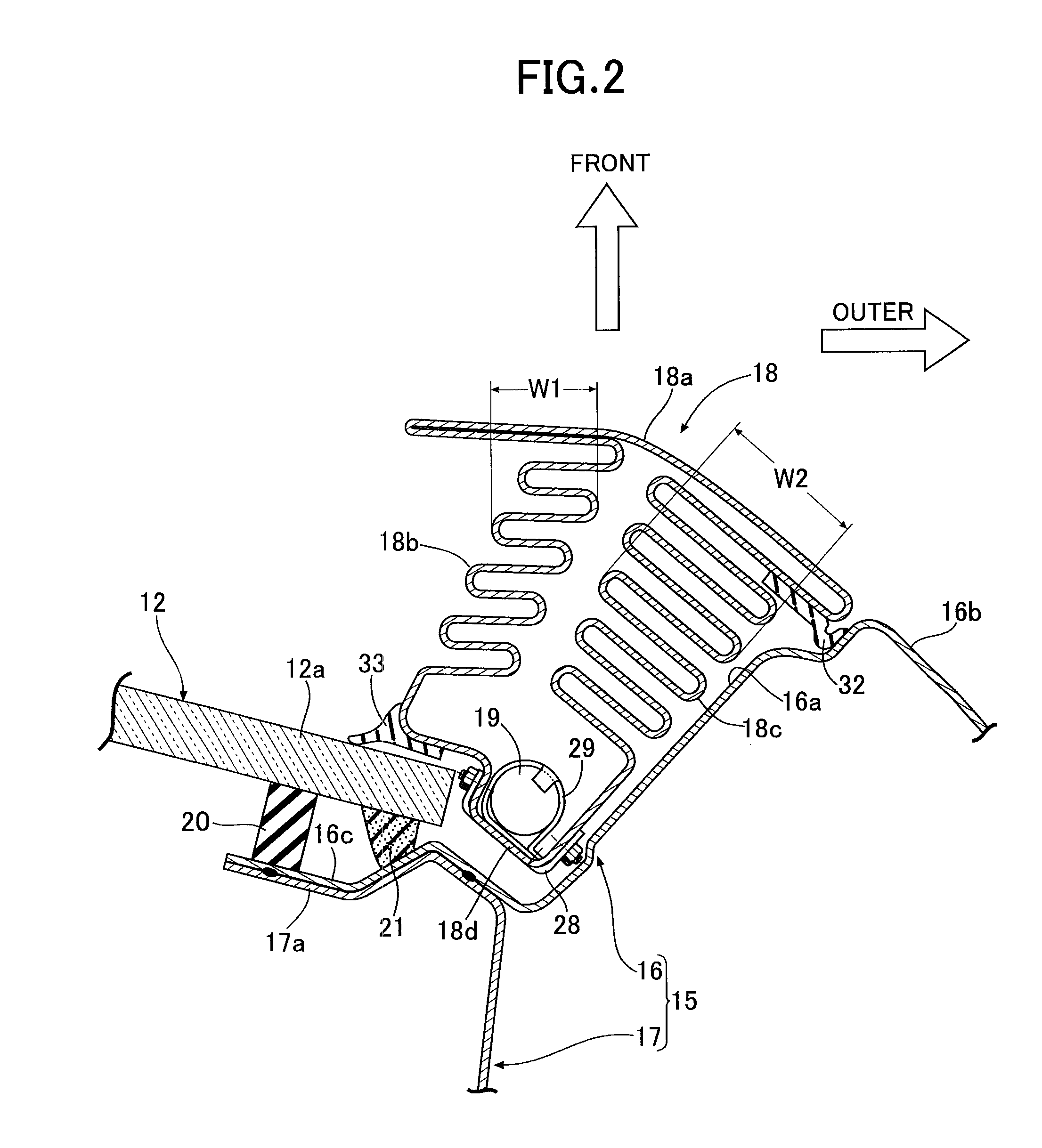
[0042]As shown in FIG. 2, the front pillar 15 is formed in a closed cross section by bonding together an outer panel 16 situated in an outer side of a vehicle body and an inner panel 17 situated in an inner side of the vehicle body. An airbag 18 made of metal, which also serves as a pillar garnish, is folded and arranged in front of a front surface 16a of the outer panel 16. The corresponding edge portion 12a of the front windshield 12 is adhered to front faces of joint sections 16c, 17a of the outer panel 16 and the inner panel 17, respectively, with an adhesive 21 with a dam rubber 20 being inter...


PUM


Abstract

Opposite end portions of an airbag made of a folded metal plate and formed into a tubular shape are capped by respective end caps and are attached to an attachment surface of a front pillar, and the airbag is deployed along the front pillar by use of gas produced by an inflator, thereby protecting by the airbag a pedestrian that collides with the front pillar. Bolts penetrating through long holes formed in the end portions of the airbag and bolt holes of the end caps are screwed to weld nuts, and thereby the end portions of the airbag are slidably supported by the end caps. Accordingly, when the airbag is deployed the long holes slide with respect to the respective bolts toward inside in a longitudinal direction of the airbag, and a tension in the longitudinal direction of the airbag is prevented from acting on a metal plate of the airbag, thereby enabling the airbag to be deployed reliably near the end caps. Therefore, it is possible to inflate the airbag evenly along its entire length and thereby enhancing the shock absorbing performance when a pedestrian collides.

Description

BACKGROUND OF THE INVENTION[0001]1. Field of the Invention[0002]The present invention relates to an airbag system comprising: an airbag made of a folded metal plate; and cap members which respectively cap opposite end portions of the airbag, the cap members being fixed to a vehicle body panel, the airbag system protecting a pedestrian by deploying the airbag by use of gas produced by an inflator.[0003]2. Description of the Related Art[0004]Japanese Patent Application Laid-open No. 2002-283939 has made publicly known an airbag system for protecting a pedestrian which is configured so that: a folded airbag made of cloth is stored inside a pillar garnish for covering a front surface of a front pillar of an automobile; in collision with a pedestrian, gas produced by an inflator is supplied to the airbag, and thus deploys the airbag along the front surface of the front pillar from a rip which is made when the pillar garnish breaks; and the pedestrian is protected with the airbag thus dep...

Claims


Application Information

Patent Timeline
02 Aug 2011
Publication
US7988183B1
IPC
B60R21/16
CPC
B60R21/36
Inventors
OKAMOTO, YUTAKA; DRAKE, ERIC