Fitness equipment cable safety apparatus

a safety apparatus and fitness equipment technology, applied in the direction of shafts, shafts, gymnastics, etc., can solve the problem of slackening of second cables, and achieve the effect of reducing or eliminating the danger of cable failur

Inactive Publication Date: 2011-08-02
TRIODYNE SAFETY SYST L L C
View PDF10 Cites 9 Cited by
  • Summary
  • Abstract
  • Description
  • Claims
  • Application Information

AI Technical Summary

Benefits of technology

[0019]This invention provides a safety mechanism for fitness equipment that use cables to lift or otherwise move resistance loads such as weight stacks. In one embodiment of this invention, a redundant duplication of the cable system is provided to distribute the load of a fitness machine, referred to as active redundancy. In another embodiment of this invention, a dormant or standby redundancy is used to provide the requisite safety. The dormant redundancy system of this invention not only reduces or eliminates the danger of cable failure, it provides the most economical use of the cable in the sense that a cable is not discarded until its life is exhausted.
[0023]Active parallel redundancy according to this invention incorporates the addition of a duplicate of the original cable system. This type of fail-safe design is very effective for preventing catastrophic failure of the cable system when, for example, the cable elements contain random defects or suffer traumatic assaults. The application of the dormant standby redundancy of this invention provides a brand new standby cable as a sentinel to keep watch over the original primary load carrying cable that supports the weight plates. Failure of the primary cable by the formation of overt faults, covert faults, or trauma, will cause a new cable to take over the function of the original load bearing cable system. When the primary load bearing cable fractures, it assumes a serpentine profile that typically wraps around the fitness machine to inform the user of a component failure. The standby cable, which is essentially brand new, will completely support the weight stack under any weight use profile. The subjectiveness and human error associated with the PM strategies are almost completely eliminated with the use of safety system of this invention.
[0024]In addition, the original cable may be used for periods much longer than, for example, one year. The cable life will be determined either by overt failures of the nylon coating which can cause excessive wear in the pulleys or upon fracture of the cable system by covert faults or external trauma. In the dormant standby redundancy, upon failure of the primary cable, the standby cable takes its place and a new cable is substituted for the standby cable. In this way, the full life of each cable is utilized, and the interval between cable replacements is greatly extended. The system of this invention is extremely flexible in its application, and can be adapted to work with various and alternative fitness machine types and configurations, independent of a particular manufacturer. The safety devices of this invention can be implemented in newly manufactured equipment or through retrofit kits in various existing machines.

Problems solved by technology

The offset cable path results in a slackening of the second cable when the cables are the same length.

Method used


Image

  • Fitness equipment cable safety apparatus
  • Fitness equipment cable safety apparatus
  • Fitness equipment cable safety apparatus

Examples


Embodiment Construction

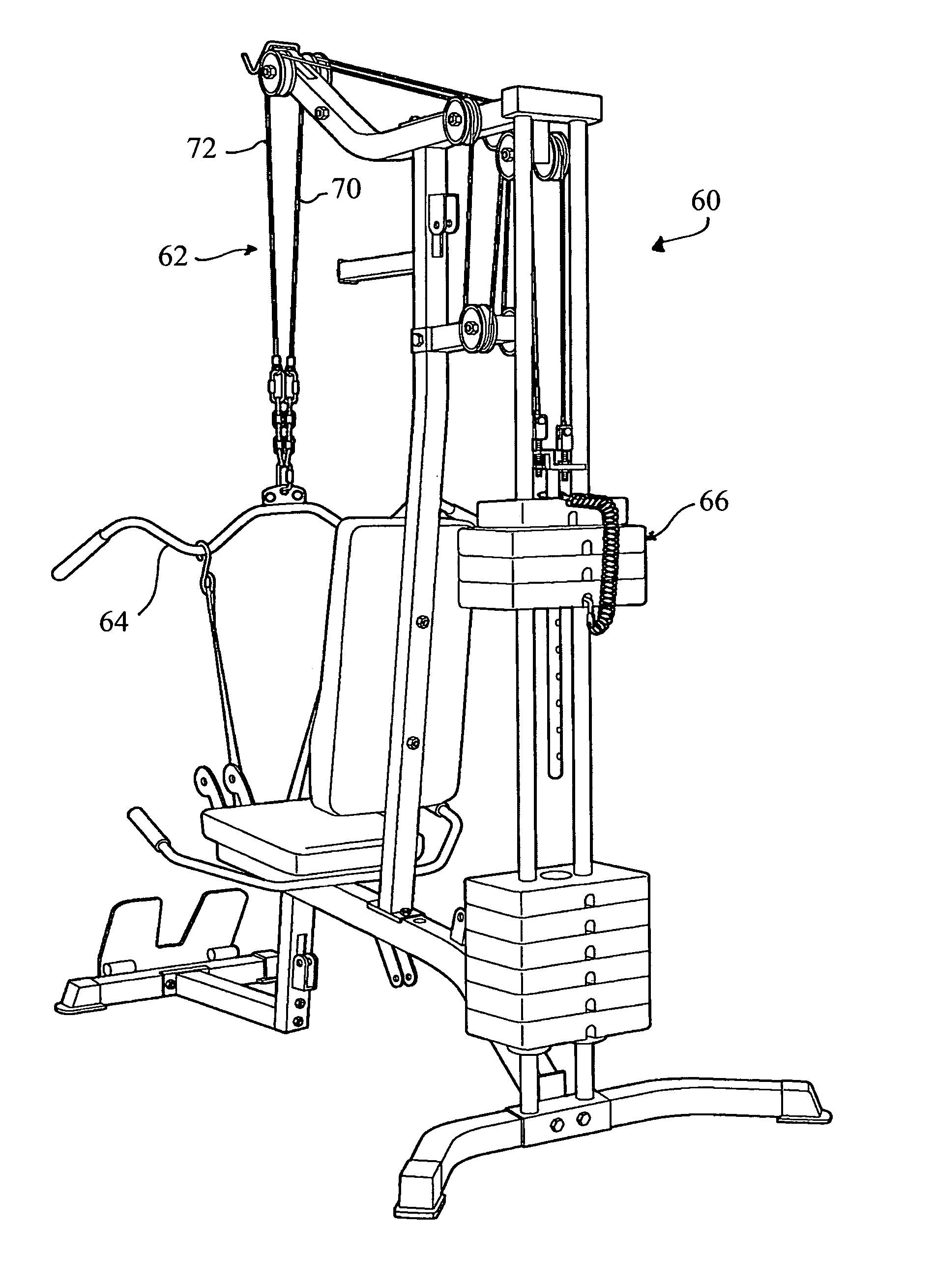
[0044]This invention provides a safety system for fitness machines that use cables to lift or otherwise move resistance loads such as weight plate stacks. The safety system of this invention desirably lengthens the life of the cables and / or provides a fail-safe design when a fault, i.e., cable break, occurs. The invention incorporates cable redundancy, by substituting two cable systems for the original one cable system.

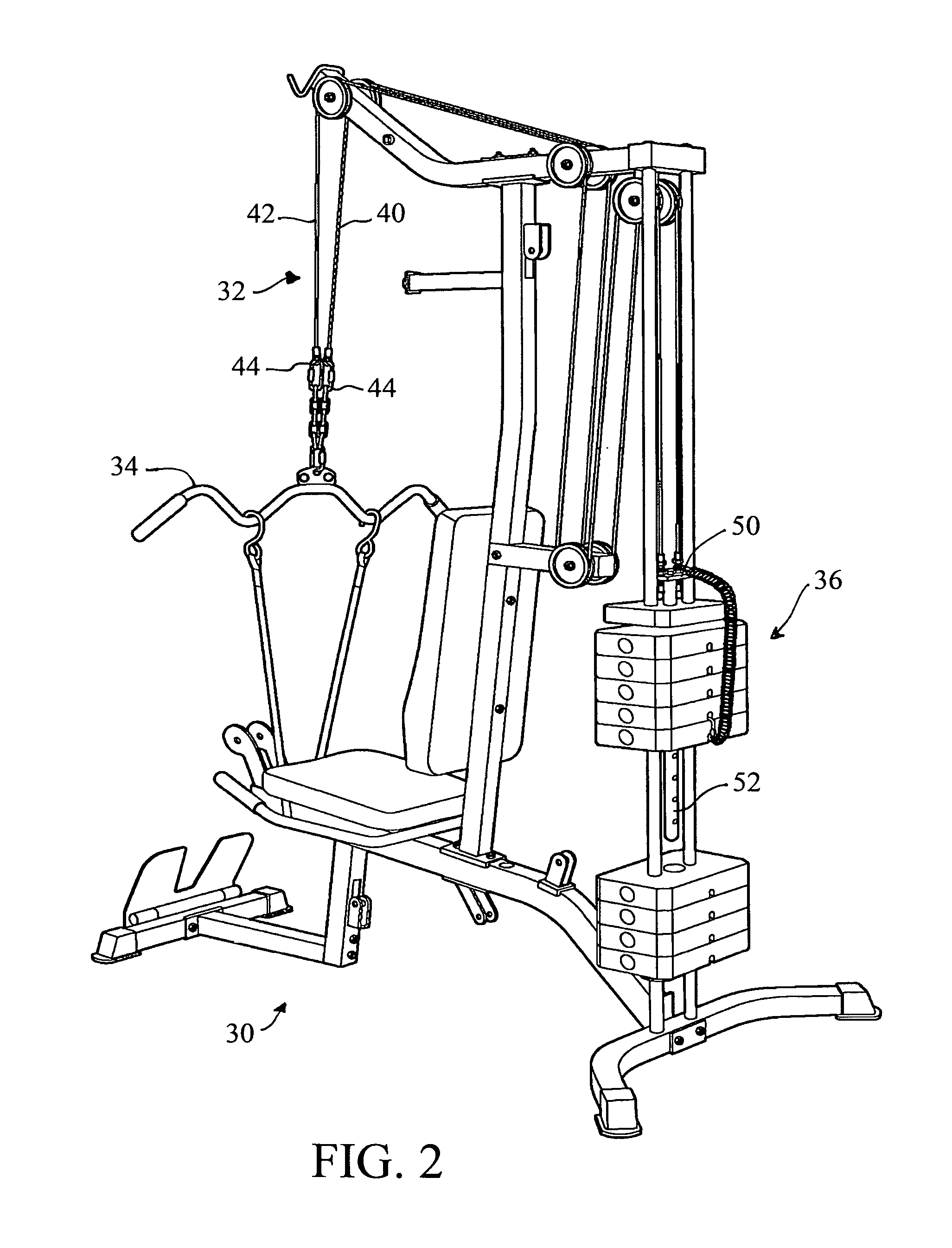
[0045]FIG. 2 illustrates an exemplary fitness device 30 including a safety cable system 32 according to one embodiment of this invention. The fitness device includes a user interface device 34 connected to a resistance load 36 by the cable system 32. The user interface device 34 is shown as a pull down bar, but can be any device or handle suitable for this or another fitness machine. Other examples of user interface devices include triceps bars, rope handles, shoulder press bars, leg extension bars or devices, leg curl bars or devices, chest press bars, and biceps cur...


PUM


Abstract

A safety cable system for a fitness device including a resistance load and a user interface device. A redundant cable apparatus connects the resistance load to the user interface device for lifting the resistance load by a force applied to the user interface device. The redundant cable apparatus comprises two cables extending in redundant cable paths between the resistance load and the user interface device. The two cables can share the resistance load or one of the cables can be dormant until failure of the other cable.

Description

CROSS REFERENCE TO RELATED APPLICATION[0001]This application claims the benefit of U.S. Provisional Patent Application Ser. No. 61 / 176,725, filed on 8 May 2009. The co-pending Provisional Patent Application is hereby incorporated by reference herein in its entirety and is made a part hereof, including but not limited to those portions which specifically appear hereinafter.BACKGROUND OF THE INVENTION[0002]1. Field of the Invention[0003]There is a family of exercise machines that provides a manual workout task requiring a user to push or pull against a resistance provided by a stack of weight plates. The weight system is usually linked with a single cable to a gripping or user interface device to produce a constant resistance. A fracture of the tensioned cable along its length or at its end connectors causes a sudden acceleration of the grip or other interface device driven by the operator's push or pull. The sudden loss of resistance often results in an exerciser pulling a heavy bar ...

Claims


Application Information

Patent Timeline
Patent Type & Authority Patents(United States)
IPC IPC(8): A63B21/062
CPCA63B21/062A63B71/0054A63B21/154Y10T74/20444A63B21/0628
Inventor BARNETT, RALPH L.
Owner TRIODYNE SAFETY SYST L L C
Why Eureka
Try Eureka