Dual staggered vertically polarized variable azimuth beamwidth antenna for wireless network

a vertical polarization variable azimuth and antenna technology, applied in antennas, antenna details, electrical equipment, etc., can solve the problems of increasing the weight and wind load of the newly installed antenna array, requiring substantial amounts of relatively expensive dielectric materials and rigid mechanical support, and increasing the size and weight of the new antenna array

Active Publication Date: 2011-08-02
TAHOE RES LTD
View PDF37 Cites 217 Cited by
  • Summary
  • Abstract
  • Description
  • Claims
  • Application Information

AI Technical Summary

Benefits of technology

[0008]In a first aspect the present invention provides an antenna for a wireless network, comprising a reflector, a first plurality of radiators pivotally coupled along a first common axis and movable relative to the reflector, and a second plurality of radiators pivotally coupled along a second common axis and movable relative to the reflector. The first plurality of radiators and the second plurality of radiators are staggered relative to each other and are configurable at different angles relative to the reflector to provide variable signal beamwidth.
[0011]The first and second plurality of radiators may respectively comprise first and second radiator elements extending from the plane of the reflector and the first and second plurality of radiators are configurable from a first setting with the first and second radiator elements oriented parallel to each other to a second setting with the elements nonparallel to each other. For example, the first setting with the elements oriented parallel to each other may have an orientation of the elements approximately 90 degrees to the plane of the reflector corresponding to a relatively wide beamwidth setting. The second setting with the elements oriented nonparallel to each other may have an orientation of the elements away from each other corresponding to a relatively narrow beamwidth setting. For example, the second setting with the elements oriented nonparallel to each other may have an orientation of the elements approximately 20 degrees away from each other, or less, corresponding to 100 degrees and 80 degrees relative to the plane of the reflector, respectively. Alternatively, the second setting with the elements oriented nonparallel to each other may have an orientation of the elements toward each other corresponding to a very wide beamwidth setting. For example, the second setting with the elements oriented nonparallel to each other may have an orientation of the elements approximately 20 degrees toward each other, or less, corresponding to 80 degrees and 100 degrees relative to the plane of the reflector, respectively. The first and second plurality of radiator elements may additionally be configurable at different angles relative to the reflector to provide variable signal beam steering.

Problems solved by technology

Such highly functional antenna arrays are typically retrofitted in place of simpler, lighter and less functional antenna arrays, while weight and wind loading of the newly installed antenna array can not be significantly increased.
Generally, highly accurate mechanical phase shifter implementations require substantial amounts of relatively expensive dielectric materials and rigid mechanical support.
Such construction techniques result in additional size and weight not to mention being relatively expensive.
Additionally, mechanical phase shifter configurations utilizing lower cost materials may fail to provide adequate passive intermodulation suppression under high power RF signal levels.

Method used


Image

  • Dual staggered vertically polarized variable azimuth beamwidth antenna for wireless network
  • Dual staggered vertically polarized variable azimuth beamwidth antenna for wireless network
  • Dual staggered vertically polarized variable azimuth beamwidth antenna for wireless network

Examples


Embodiment Construction

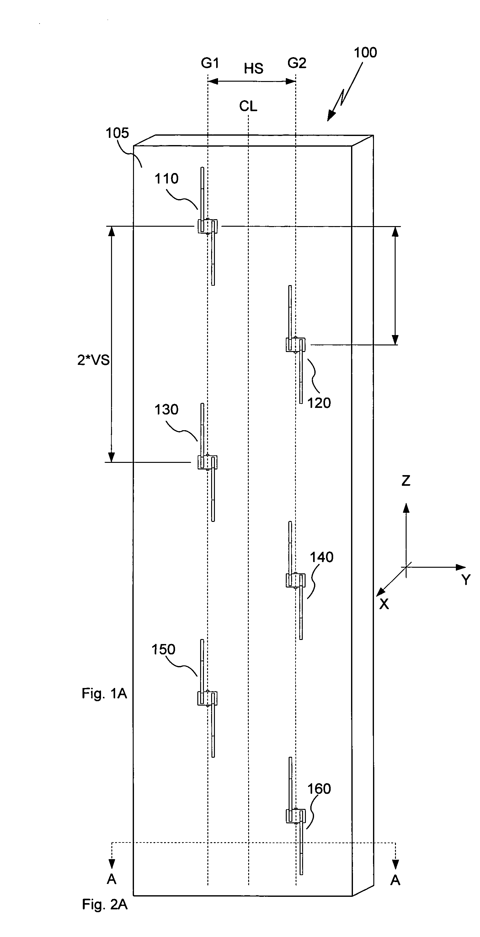
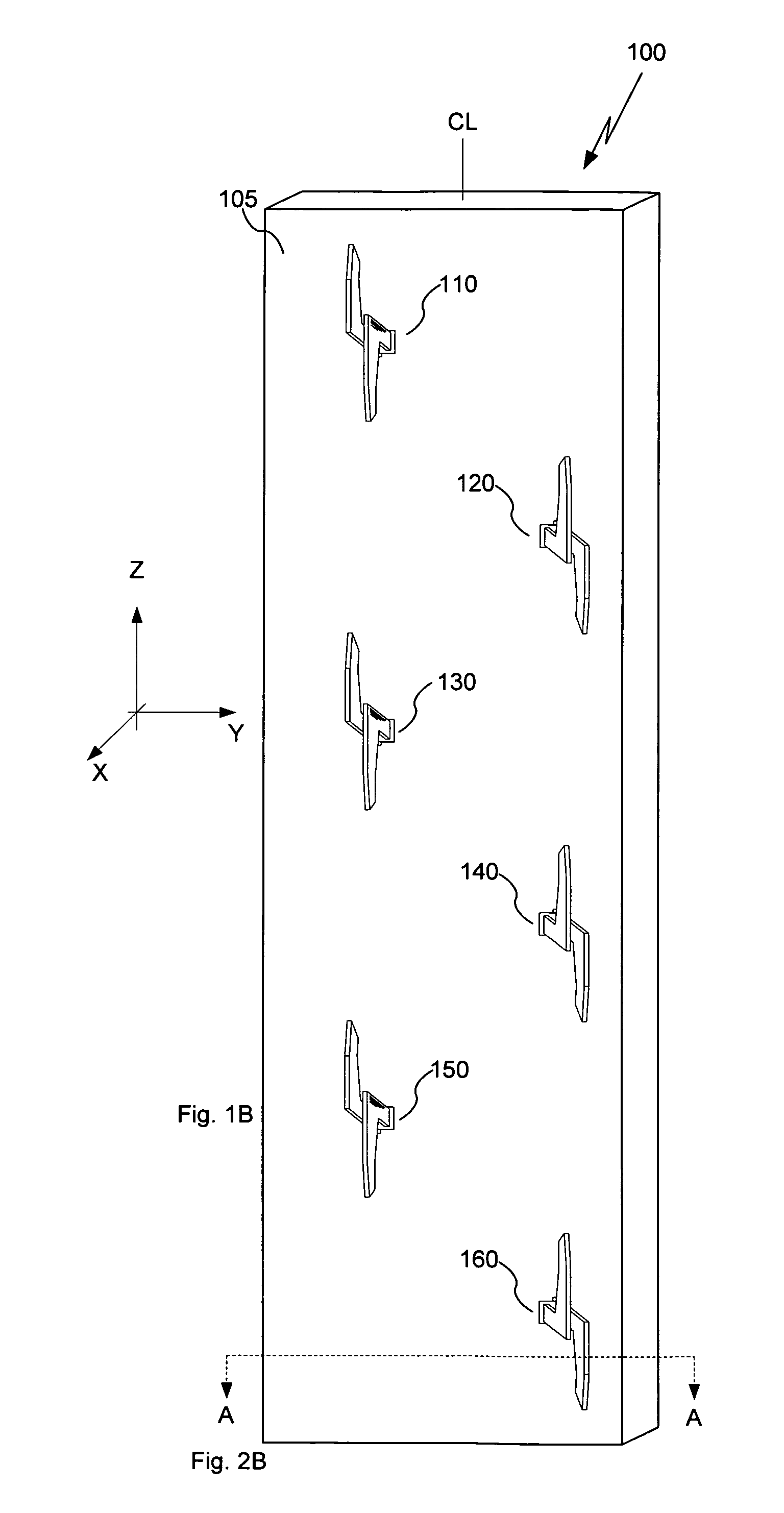
[0028]Reference will be made to the accompanying drawings, which assist in illustrating the various pertinent features of the present invention. The present invention will now be described primarily in solving aforementioned problems relating to use of a plurality of mechanical phase shifters, it should be expressly understood that the present invention may be applicable in other applications wherein beamwidth control is required or desired. In this regard, the following description of a dual stagger, vertically polarized antenna array equipped with pivotable radiating elements is presented for purposes of illustration and description. Furthermore, the description is not intended to limit the invention to the form disclosed herein. Accordingly, variants and modifications consistent with the following teachings, and skill and knowledge of the relevant art, are within the scope of the present invention. The embodiments described herein are further intended to explain modes known for p...


PUM


Abstract

An antenna system for wireless networks having a dual stagger antenna array architecture is disclosed. The antenna array contains a number of driven radiator elements that are spatially arranged in two vertically aligned groups each having pivoting actuators so as to provide a controlled variation of the antenna array's azimuth radiation pattern.

Description

[0001]The present application claims priority under 35 USC section 119(e) to U.S. Provisional Patent Application Ser. No. 60 / 906,161, filed Mar. 8, 2007, the disclosure of which is herein incorporated by reference in its entirety.BACKGROUND OF THE INVENTION[0002]1. Field of the Invention[0003]The present invention relates in general to communication systems and components. More particularly the present invention is directed to antennas for wireless networks.[0004]2. Description of the Prior Art and Related Background Information[0005]Modern wireless antenna implementations generally include a plurality of radiating elements that may be arranged over a reflector plane defining a radiated (and received) signal beamwidth and azimuth scan angle. Azimuth antenna beamwidth can be advantageously modified by varying amplitude and phase of a Radio Frequency (RF) signal applied to respective radiating elements. Antenna azimuth beamwidth has been conventionally defined by Half Power Beam Width...

Claims


Application Information

Patent Timeline
Patent Type & Authority Patents(United States)
IPC IPC(8): H01Q3/00H01Q21/00
CPCH01Q1/246H01Q3/06H01Q3/18H01Q3/30H01Q19/108H01Q21/062
Inventor DENG, GANG YIVASSILAKIS, BILLHUNTON, MATTHEW J.RABINOVICH, ALEXANDER
Owner TAHOE RES LTD
Why Eureka
Try Eureka