
Hybrid robust predictive optimization method of power system dispatch

a power system and predictive optimization technology, applied in the field of microgrids, can solve problems such as the cost of generation models for producing electricity

Active Publication Date: 2011-08-02
GENERAL ELECTRIC CO
View PDF8 Cites 44 Cited by
  • Summary
  • Abstract
  • Description
  • Claims
  • Application Information

AI Technical Summary

Benefits of technology

"The patent describes a system and method for controlling a microgrid, which is a small power grid that can be connected to a larger power grid. The system includes multiple microgrid assets, such as generators and loads, that are connected to the microgrid. The system uses a predictive optimization control algorithm to adjust the operation of these assets in real-time, based on predicted future conditions, to optimize the overall operation of the microgrid and improve its efficiency. The technical effect of this system is to enable better management of microgrids, leading to improved reliability, reduced costs, and improved performance."

Problems solved by technology

The generation model represents the cost of producing electricity as a function of power generated and the generation capability of each unit.

Method used


Image

  • Hybrid robust predictive optimization method of power system dispatch
  • Hybrid robust predictive optimization method of power system dispatch
  • Hybrid robust predictive optimization method of power system dispatch

Examples


Embodiment Construction

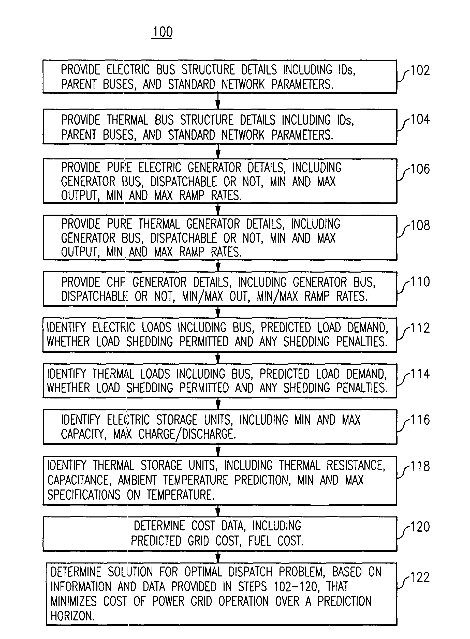
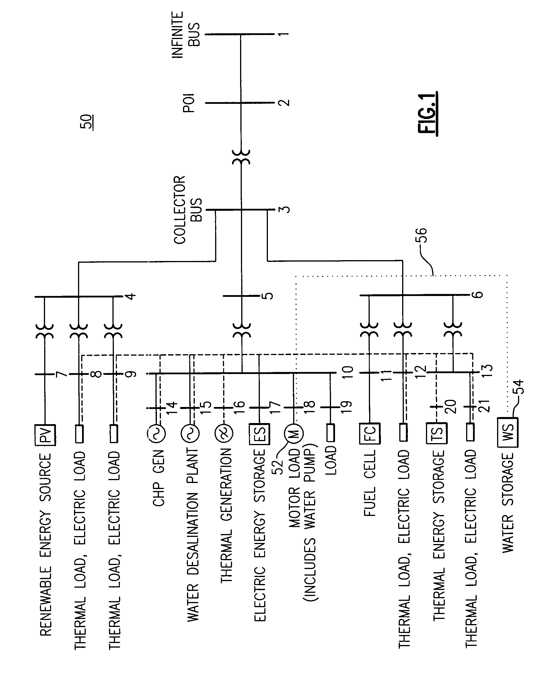
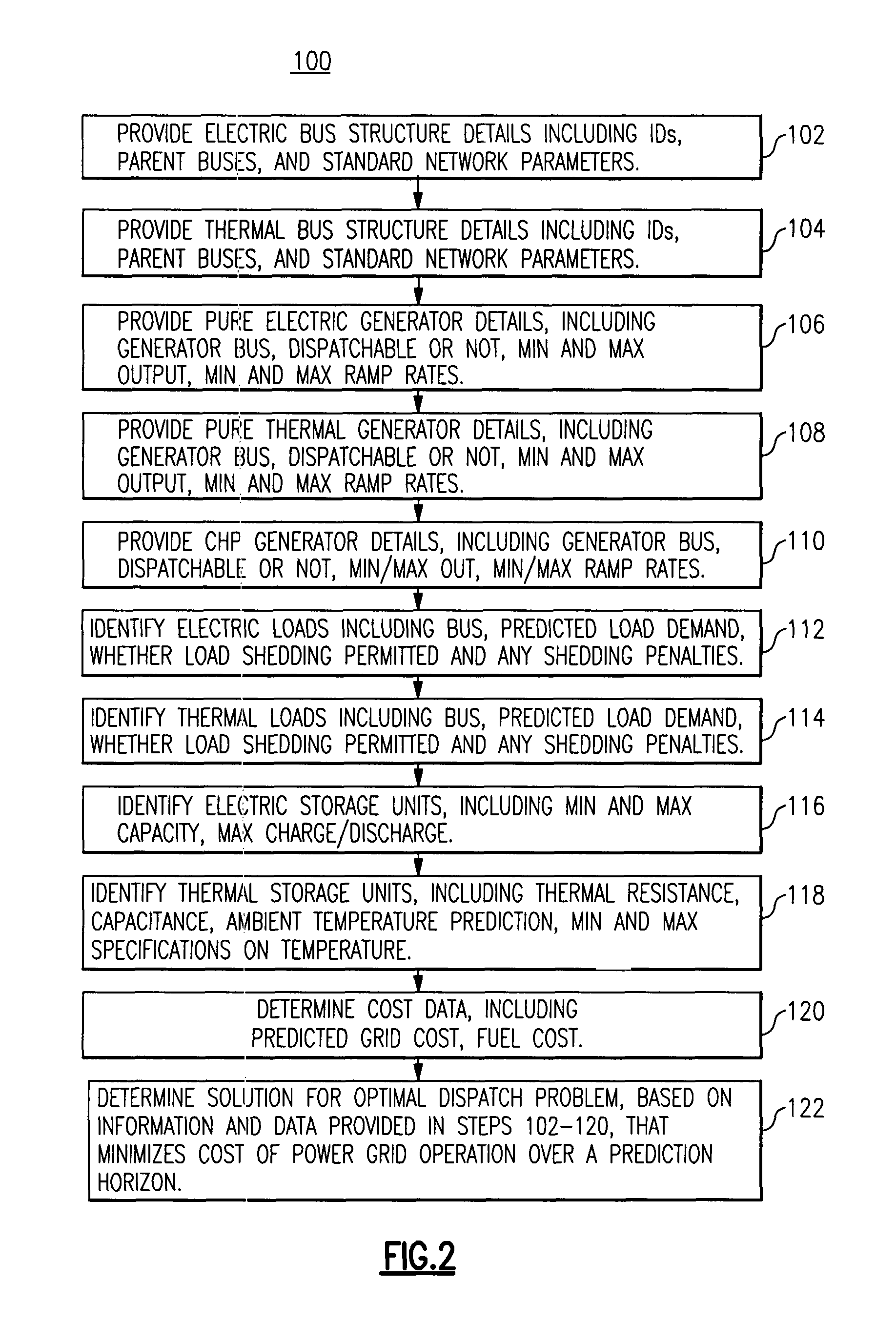
[0025]FIG. 1 is a diagrammatic representation of a microgrid 50 that is useful to describe a predictive approach for an optimal dispatch problem involving both heat and electric power, according to one embodiment. In this diagram, electric and thermal loads (e.g. buildings) are connected to buses 8, 9, 12 and 21 of the electric grid 50. The thermal loads can be supplied either by the combined heat and power units (CHPs), such as shown on bus 14 of the electrical grid 50, or they may be supplied, for example, by boilers (not shown in the diagram). In practice, the electrical and thermal loads, as well as the electric power generation are variable. If the predicted values of these quantities are known ahead of time, it is possible to incorporate them into an optimization strategy which minimizes the total, predicted cost of operation (over a time horizon of a predetermined number of hours, known as the prediction horizon). This predicted cost includes fuel costs (for running the CHPs ...


PUM


Abstract

A method of power system dispatch control solves power system dispatch problems by integrating a larger variety of generation, load and storage assets, including without limitation, combined heat and power (CHP) units, renewable generation with forecasting, controllable loads, electric, thermal and water energy storage. The method employs a predictive algorithm to dynamically schedule different assets in order to achieve global optimization and maintain the system normal operation.

Description

STATEMENT REGARDING FEDERALLY SPONSORED RESEARCH & DEVELOPMENT[0001]This invention was made with U.S. Government support under contract number DE-FC02-05CH11349 awarded by the Department of Energy. The Government has certain rights in the invention.BACKGROUND[0002]The invention relates generally to microgrids and more particularly to a predictive control strategy for management and control of microgrids having arbitrary numbers of assets and arbitrary system topologies.[0003]A microgrid is defined generally as an aggregation of controllable and uncontrollable asserts which may comprise, for example, electrical generators, loads, and storage devices. Electrical generators in a microgrid typically include, for example, non-conventional energy sources such as micro turbines, wind turbines, photovoltaic systems, fuel cells, or hydrogen fed reciprocating engines. Microgrids may supply power, for example, to shopping centers, industrial parks, college campuses or villages.[0004]Economic D...

Claims


Application Information

Patent Timeline
Patent Type & Authority Patents(United States)
IPC IPC(8): H02J3/14
CPCG06Q10/06G06Q30/0202Y04S10/54Y04S10/545Y04S50/14Y02E40/76Y02E40/70Y04S10/50Y02P80/14Y02P80/15
Inventor CHANDRA, RAMU SHARATLIU, YANBOSE, SUMITDE BEDOUT, JUAN MANUEL
Owner GENERAL ELECTRIC CO
Learn More