Visible light and IR combined image camera

a combined image camera and visible light technology, applied in the direction of radiation controlled devices, optical radiation measurement, distance measurement, etc., can solve the problems of color change, inability to accurately detect the change, and difficulty in interpreting infrared-only images

Active Publication Date: 2011-08-09
JOHN FLUKE MFG CO INC
View PDF59 Cites 56 Cited by
  • Summary
  • Abstract
  • Description
  • Claims
  • Application Information

AI Technical Summary

Benefits of technology

Certain embodiments of the invention include a hand-held camera for producing IR images, where the camera includes an IR camera module supported by a camera housing and having IR sensors and IR optics. The IR sensors include an array of IR sensors for sensing IR images of a target scene. The camera in such embodiments also includes a display supported by the camera housing for displaying por

Problems solved by technology

Because the resulting IR image is based on the target's temperature, and because the colors or levels displayed by the camera do not typically correspond to the visible light colors of the scene, it can be difficult, especially for novice users of such a device, to accurately relate features of interest (e.g. hot spots) in the IR scene with their corresponding locations in the visible-light scene viewed by the operator.
In applications where the infrared scene contrast is low, infrared-only images may be especially difficult to interpret.
However, sometimes the hot or cold spot may be small and the color change may go unnoticed.
Even with the color change and the hot spot indications, it can be dif

Method used


Image

  • Visible light and IR combined image camera
  • Visible light and IR combined image camera
  • Visible light and IR combined image camera

Examples


Embodiment Construction

System Description

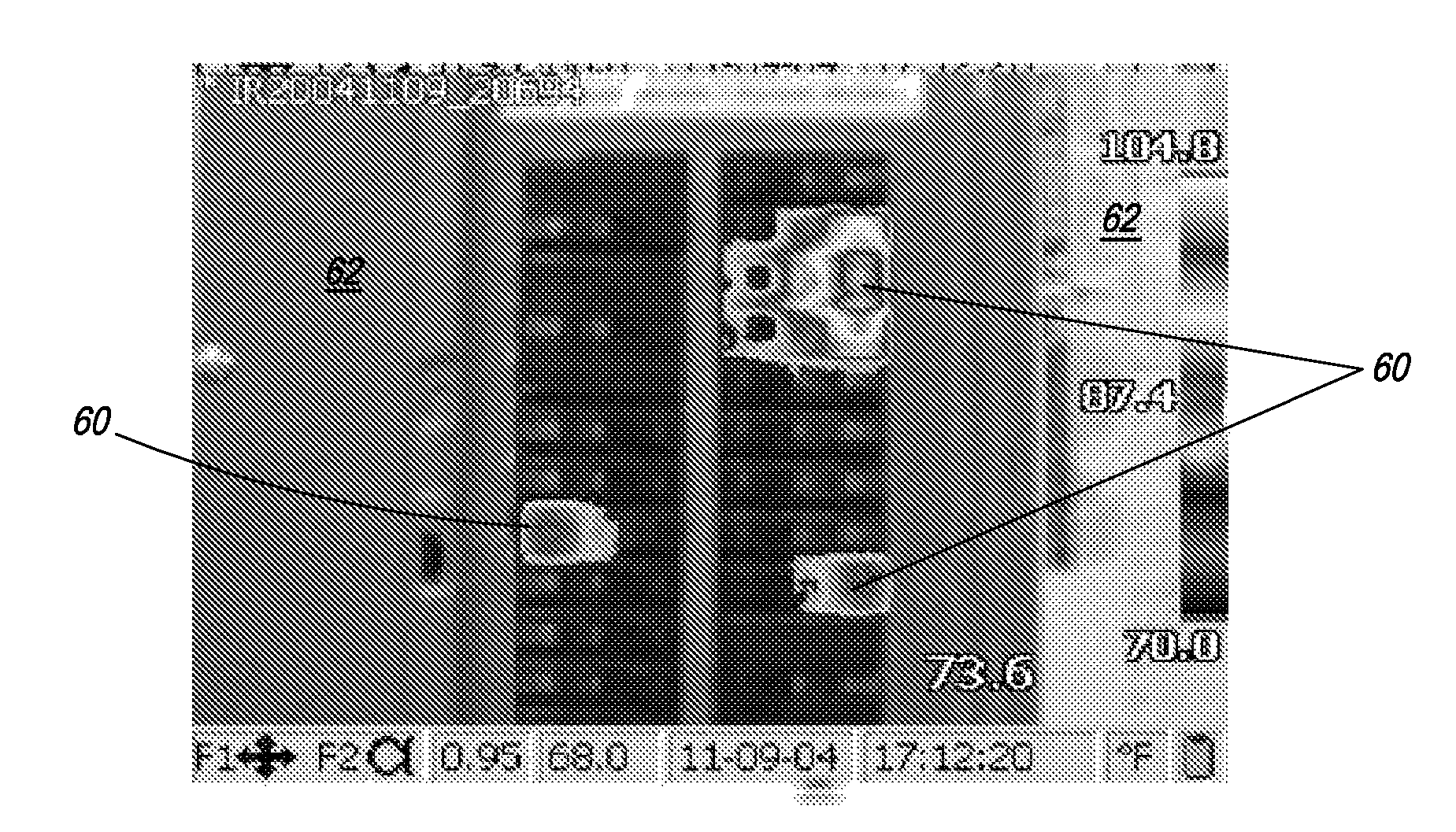
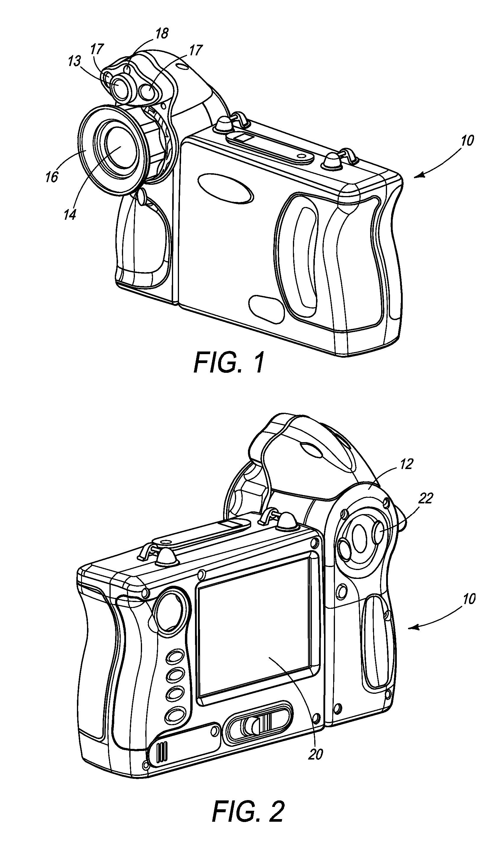
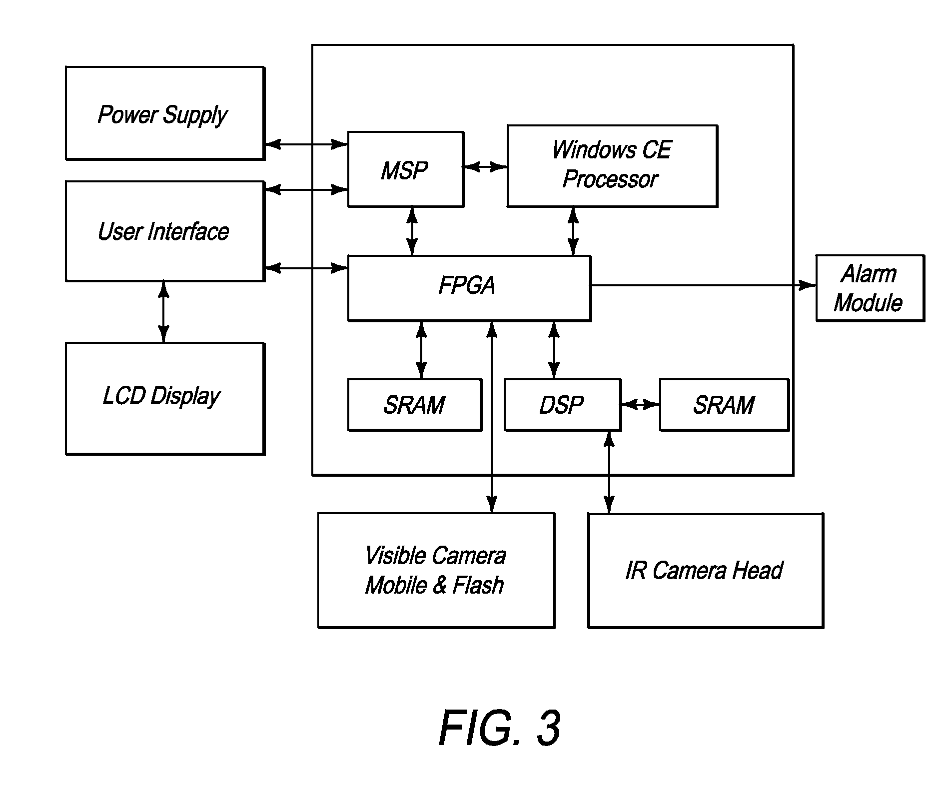
FIGS. 1 and 2 are perspective views of the front and the back of a camera 10 according to an embodiment of the invention. The housing includes an infrared camera module and a visible-light camera module. In particular, the camera 10 includes a camera housing 12, a Visible-Light (VL) lens 13, an infrared lens 14, focus ring 16 and a laser pointer 18 as well as various electronics located within the housing as will be described with reference to FIG. 3. In an embodiment, an LED torch / flash 17 is located on each side of the VL lens 13 to aid in providing enough light in dark environments. A display 20 is located on the back of the camera so that infrared images, visible light images and / or blended images of Infrared and Visible-Light may be viewed. In addition, target site temperature (including temperature measurement spot size) and distance readings may be displayed. Also located on the back of the camera are user controls 22 to control the display mode and activate...


PUM


Abstract

An infrared (IR) light camera or sensor that provides temperature alarms. The temperature alarms may be audible, vibrational, and visual to indicate when a portion of the IR image meets user-defined alarm criteria. Visual alarms may be provided by displaying on a camera display unit the portions of the IR image that meet the alarm criteria.

Description

BACKGROUNDMany infrared cameras today produce an image (IR image) of a scene using only energy in the far-infrared portion of the electromagnetic spectrum, typically in the 8-14 micron range. Images obtained using these cameras assign colors or gray-levels to the pixels composing the scene based on the intensity of the IR radiation reaching the camera's sensor elements. Because the resulting IR image is based on the target's temperature, and because the colors or levels displayed by the camera do not typically correspond to the visible light colors of the scene, it can be difficult, especially for novice users of such a device, to accurately relate features of interest (e.g. hot spots) in the IR scene with their corresponding locations in the visible-light scene viewed by the operator. In applications where the infrared scene contrast is low, infrared-only images may be especially difficult to interpret.An infrared scene is a result of thermal emission and, not all, but most infrare...

Claims


Application Information

Patent Timeline
IPC IPC(8): G01T1/24H01L25/00A61B6/00
CPCG01C3/08H04N5/332G01J5/0265G01J5/0295G01J5/0859G01J5/089G01J5/0896H01L27/14618H01L27/14625H04N5/2254H04N5/2258H04N5/23212H04N5/23293H04N5/33G01J5/025H01L2924/0002G01J5/07H04N23/45H04N23/67H04N23/635H04N23/11H01L2924/00
Inventor JOHNSON, KIRK R.MCMANUS, THOMASPRATREU, JOHN W.
Owner JOHN FLUKE MFG CO INC
Why Eureka
Try Eureka