Flood barrier system

a technology of flood barrier and floodwater, applied in the direction of coastline protection, shutters/movable grilles, foundation engineering, etc., can solve the problems of inconvenient installation, large damage, and floodwater occasionally inundating homes, offices and commercial and factory buildings, etc., to facilitate the installation process, and facilitate the assembly process. stable and secure

Active Publication Date: 2011-08-23
PRESRAY
View PDF41 Cites 17 Cited by
  • Summary
  • Abstract
  • Description
  • Claims
  • Application Information

AI Technical Summary

Benefits of technology

[0007]In accordance with one aspect of the invention, the individual barrier elements, which may be formed of extruded aluminum sections, are shaped such that each barrier element forms a novel mechanical interlock with the barrier element below. The arrangement allows an upper barrier element to be initially engaged with the element below and then pivoted into an installed position in a simple and highly expeditious manner. This both facilitates the installation process and makes the assembly more stable and secure while the installation is under way.
[0009]The barrier structure of the invention also advantageously incorporates a vertically acting clamping arrangement that is mounted above the uppermost barrier element, at each side thereof, arranged to bear downwardly on the entire stack of barrier elements to assure good sealing pressure between vertically adjacent elements. In the structure of the present invention, such vertically acting clamping mechanisms are slideably installed and removed from the same vertical channels that receive the clamping assemblies. This enables the clamping arrangements to be quickly installed after the last barrier element is in place, and just as quickly removed and remotely stored when the flood threat has terminated.

Problems solved by technology

In certain areas, homes, offices and commercial and factory buildings occasionally are inundated by flood waters.
In this respect, water flowing in through a single unprotected opening, even though others are protected, can inundate the entire structure and cause great damage.

Method used


Image

  • Flood barrier system
  • Flood barrier system
  • Flood barrier system

Examples


Embodiment Construction

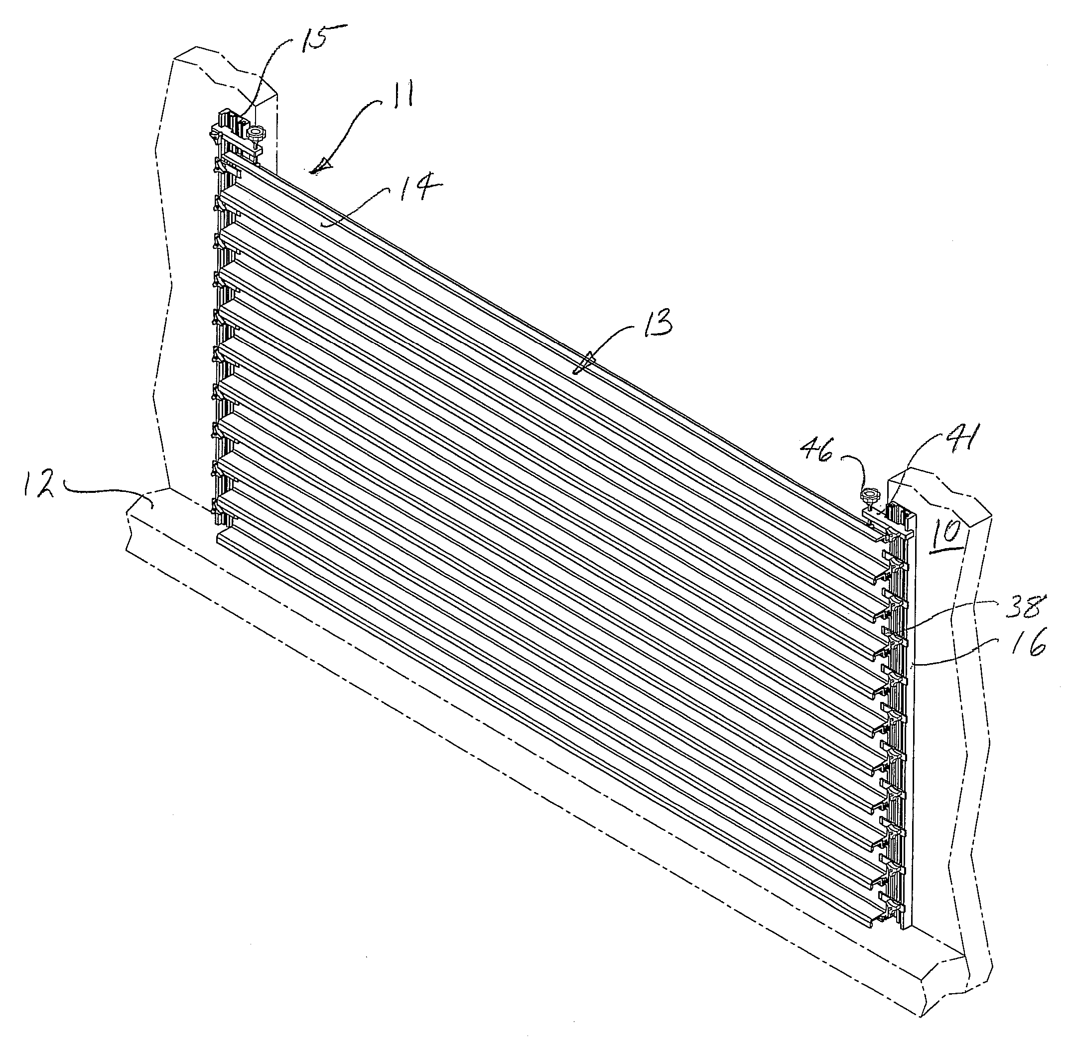
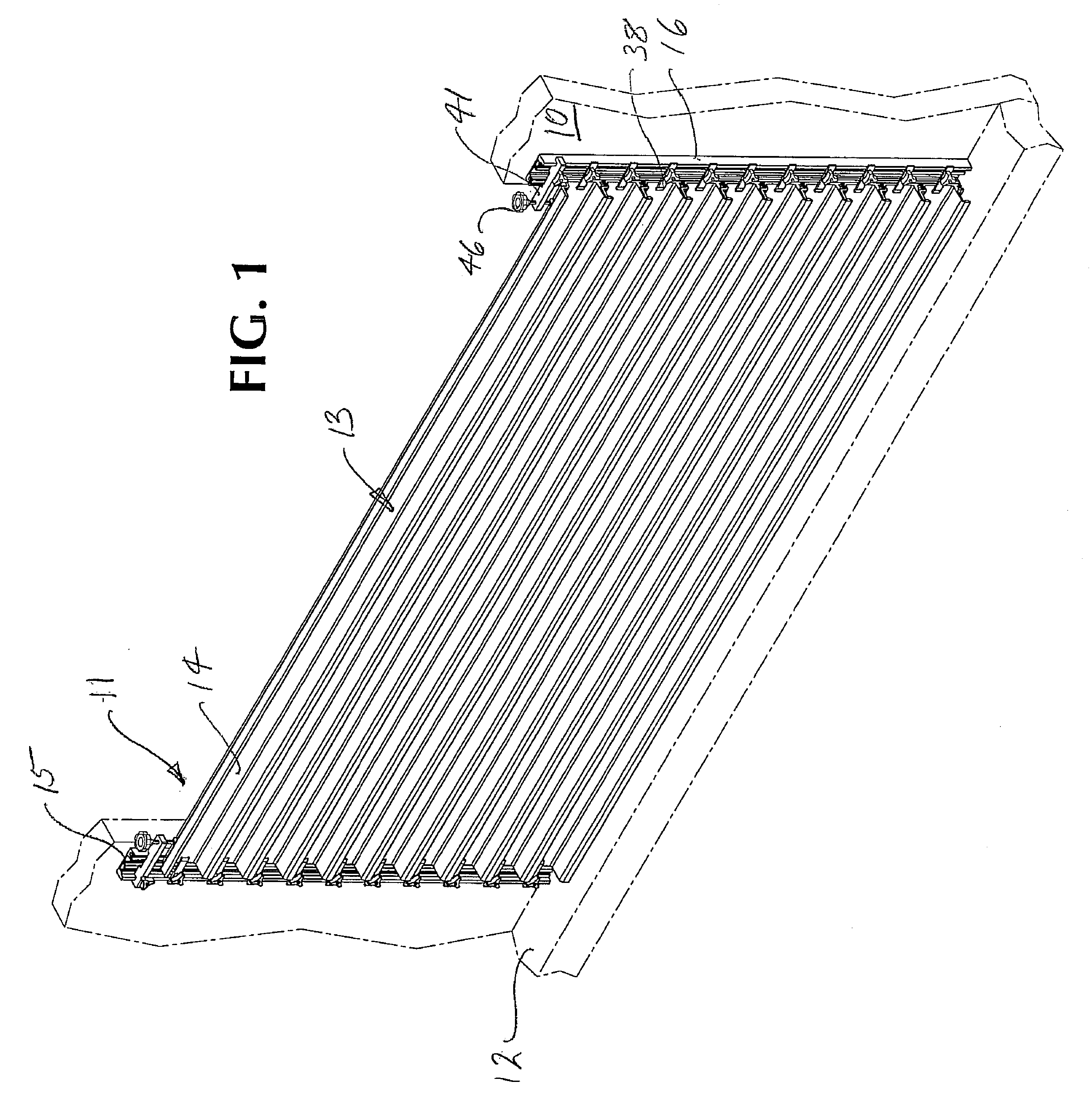
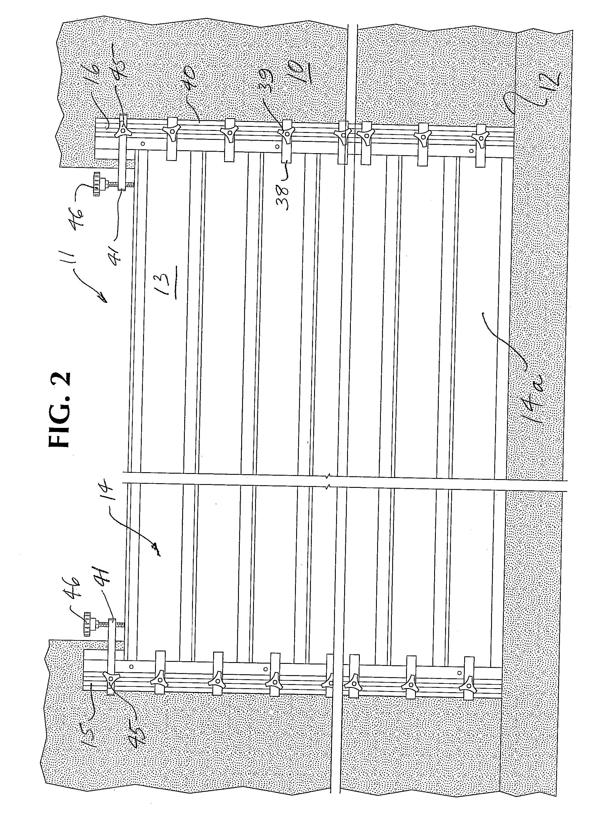
[0019]Referring now to the drawings, the reference numeral 10 designates generally a building structure having a large door opening 11 therein which extends upward from a floor or threshold 12. A flood barrier assembly 13 (FIGS. 1 and 3) constructed in accordance with the invention is shown as installed in the doorway 11 to provide a barrier against inundation by flood waters. The barrier is comprised of a plurality of individual, horizontally elongated barrier elements 14, stacked one on top of the other and extending across the full width of the door opening 11. As will become apparent, a flood barrier of any suitable height may be constructed, within the maximum capacity of the installation, by assembling a predetermined number of the barrier elements 14 in a vertical stack.

[0020]In the illustrated form of the invention, vertical rails 15, 16 are mounted on the front face of the building structure 10, at each side of the door opening 11. Typically, the rails 15 are permanently at...


PUM


Abstract

A flood barrier system for temporarily sealing an opening in a wall structure against the inflow of flood waters. The system comprises a plurality of elongated, horizontally disposed barrier elements of a length somewhat greater than the width of the opening. The barrier elements are stacked vertically, one upon the other against the outer face of the wall structure. End clamps engage opposite ends of the individual barrier elements to press them snugly against the outer surface of the wall, providing seals along the opposite vertical side edges of the opening. The barrier elements incorporate a unique interlocking configuration that simplifies and expedites assembly of a flood barrier and strengthens the integrity of the assembled structure. Improved and simplified arrangements are provided for clamping the ends of the barrier elements and for applying downward pressure to the assembled barrier. The resulting structure is more economical to provide and maintain and is more quickly assembled in the often emergency circumstances in which it is required.

Description

RELATED APPLICATIONS[0001]This application is related to Jason W. Smith U.S. application Ser. No. 11 / 391,110, filed Mar. 28, 2008, now U.S. Pat. No. 7,552,565, granted Jun. 30, 2009, the disclosure of which is incorporated herein by reference.BACKGROUND OF INVENTION[0002]In certain areas, homes, offices and commercial and factory buildings occasionally are inundated by flood waters. To minimize damage from rising flood waters, such structures can utilize temporary flood barriers that are installed in low level door and window openings, to seal those openings against inflow of water into the structure. Various barrier systems are available for this purpose, with a wide variety of design features dictated to some extent by the size of the opening to be protected.[0003]For the protection of a relatively wide doorway, for example, against flood waters that may rise to a considerable level above the bottom of the door opening, the barrier system must have considerable structural soundnes...

Claims


Application Information

Patent Timeline
Patent Type & Authority Patents(United States)
IPC IPC(8): E06B3/26
CPCE06B9/02E06B2009/007
Inventor FISHER, WAYNE
Owner PRESRAY
Why Eureka
Try Eureka