Ceiling vent diffuser

a ceiling vent and diffuser technology, applied in the field of ceiling vents, can solve the problems of effectively blocking airflow at a particular workstation, and relatively unaffected overall temperature of the building, and achieve the effects of not reducing the overall volume of air flowing out of the vent, rapid installation and removal, and rapid blocking of airflow

Inactive Publication Date: 2011-08-23
AIRVISOR
View PDF21 Cites 5 Cited by
  • Summary
  • Abstract
  • Description
  • Claims
  • Application Information

AI Technical Summary

Benefits of technology

[0008]The device is complementary shaped to a region of the diffuser. If a typical square diffuser is viewed from the position of the mouth of the vent pipe to which the diffuser is attached, then the diffuser may be considered to have four directional quadrants out of which air flows. Those quadrants are effectively directed toward the north, the south, the east and the west. Under normal operating conditions, air radiates outwardly and downwardly from the vent and through the diffuser in all four quadrants. The device of the present invention provides a mechanism for blocking airflow in a selected one of the quadrants. When installed, the device blocks the openings in that region and substantially prevents air from flowing out of the openings. The device can be quickly and easily installed and removed and thereby allows for rapid blocking of the airflow in any one direction from the diffuser. The airflow out of the remaining three quadrants is increased proportionately, but the overall volume of air flowing out of the vent is not reduced. Consequently, the airflow at a particular workstation, for example, may be effectively blocked, but the overall temperature of the building is relatively unaffected.

Problems solved by technology

Consequently, the airflow at a particular workstation, for example, may be effectively blocked, but the overall temperature of the building is relatively unaffected.

Method used


Image

  • Ceiling vent diffuser
  • Ceiling vent diffuser
  • Ceiling vent diffuser

Examples


Embodiment Construction

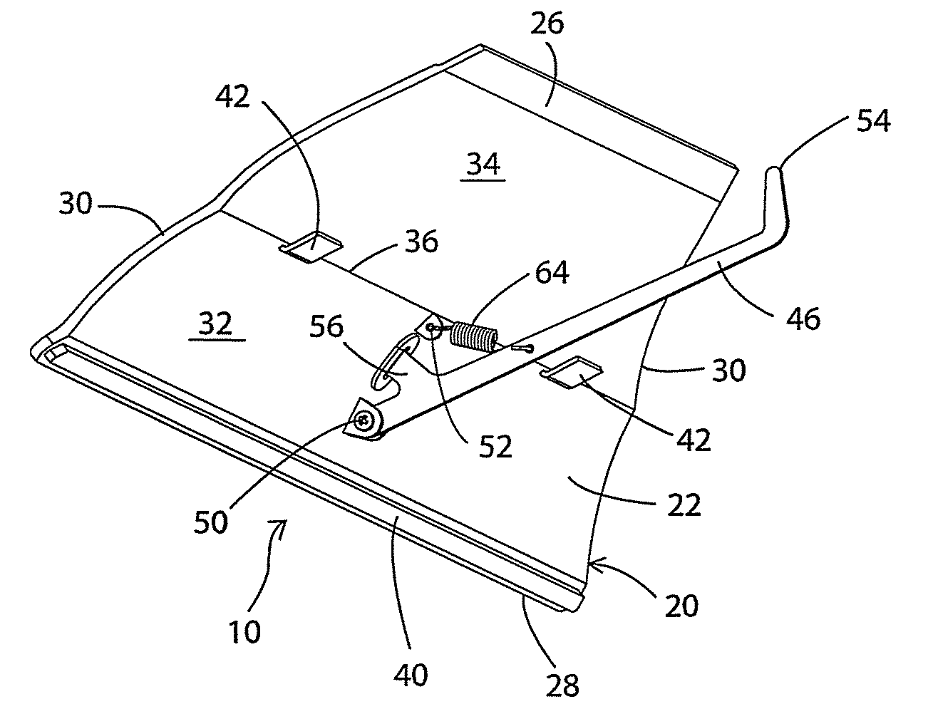
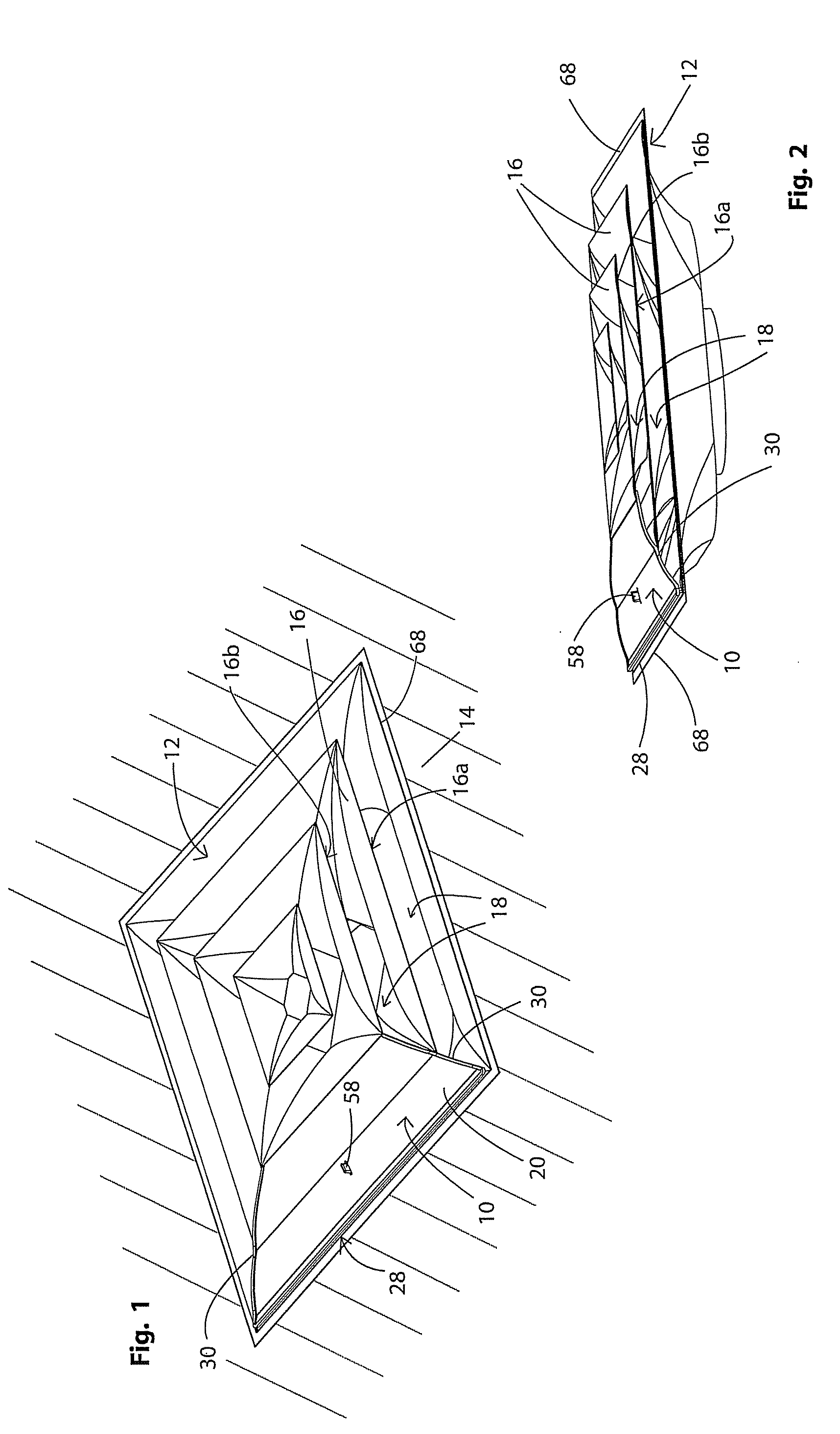
[0030]Referring to FIGS. 1-14 there is shown a vent diffuser cover in accordance with the present invention and generally indicated at 10. Cover 10 is designed to be engaged with a vent diffuser 12 to change the airflow pattern therefrom. The vent diffuser 12 is positioned in front of a vent (not shown) in the ceiling 14 and typically is either square or circular in shape. Diffuser 12 is shown as having four vanes 16 and openings 18 therebetween through which air can flow.

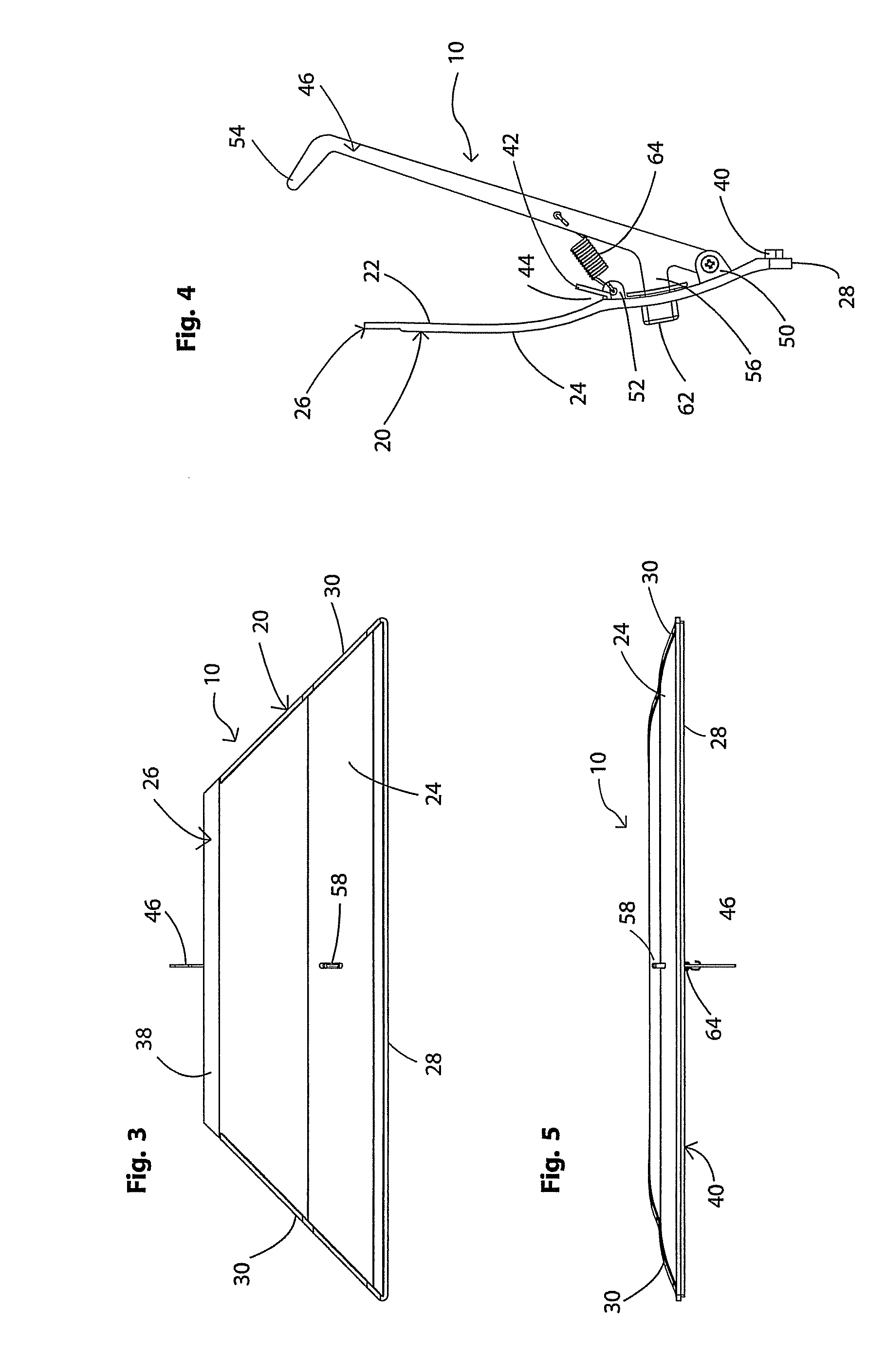
[0031]In accordance with a specific feature of the present invention, cover 10 comprises a flexible member 20 that preferably is manufactured from a plastic material. Flexible member 20 may be transparent so that it is not easily noticed on vent diffuser 12 or may be opaque and colored so that it blends into vent diffuser 12 or colored so that it is easily seen.

[0032]Flexible member 20 has an inner surface 22, an outer surface 24, interior edge 26, exterior edge 28 and side edges 30. Interior edge 26 is shorter in ...


PUM


Abstract

A device for altering the airflow pattern from a ceiling vent diffuser. The device comprises a flexible member that is secured to a diffuser vane by a spring-biased hook and one or more tabs. A release button on the outer surface of the device is depressed to pivot the hook out of engagement with the vane. The device is complementary shaped to a region of the diffuser. When installed, the device blocks the openings in that region and substantially prevents air from flowing out of the openings. One or more devices may be installed in selected regions to block airflow from those selected regions. A plurality of devices may be utilized to completely prevent airflow from the diffuser.

Description

BACKGROUND OF THE INVENTION[0001]1. Technical Field[0002]This invention generally relates to air circulation systems for buildings. More particularly, the invention relates to ceiling vents. Specifically, the invention relates to a cover that is detachably connectable to a ceiling vent diffuser to block airflow from a region of the diffuser.[0003]2. Background Information[0004]Most industrial and commercial buildings have 24″×24″ square ceiling vent diffusers that are mounted on drywall or T-bar ceilings. Occasionally, buildings may be provided with circular vent diffusers, but these are less common than the square version. The vent diffusers are standardized to fit in the 24″ T-bar ceiling spacing and can be made with three or four vents through which heated or cooled air is introduced into the room. The diffusers alter the direction of the air flowing out of the vent so that the air does not flow straight down into the room and at right angles to the ceiling. Instead, the diffuser...

Claims


Application Information

Patent Timeline
Patent Type & Authority Patents(United States)
IPC IPC(8): A47H13/00A47G5/00
CPCF24F13/075F24F13/14
Inventor BROWN, CHAD A.DICKIE, ROBERT G.
Owner AIRVISOR
Why Eureka
Try Eureka