
No-slide pin spot

a pin spot and no slide technology, applied in the field of no slide pin spot, can solve the problems of uneven wear in comparison, significant rise in the standing out of range pin, and achieve the effect of quick installation and removal, and easy installation

Active Publication Date: 2010-04-27
KEGEL LLC
View PDF3 Cites 2 Cited by
  • Summary
  • Abstract
  • Description
  • Claims
  • Application Information

AI Technical Summary

Benefits of technology

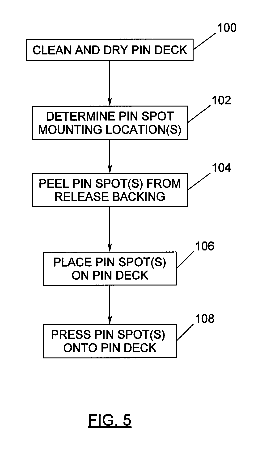
"The invention is a bowling pin spotting article that can be easily installed and removed to provide a high friction support surface for bowling pins. The pin spot is made of a plastic film material with an adhesive applied to the bottom, and can be quickly and easily removed and replaced with a new pin spot. The pin deck can also have a pattern of no-skid pin spots to reduce out-of-range bowling pins. The method involves cleaning the surface of the pin deck, adhering the frictional material piece to the surface in a desired location, and can be used with different numbers of bowling pins."

Problems solved by technology

The constant, repetitive placing of bowling pins on the pin spots caused them to wear unevenly in comparison to the surrounding surfaces of the bowling lane.
However, one problem, the standing out-of-range pin, has risen significantly due to the increased use of lane conditioners and oils.
The out-of-range pin can cause equipment problems, especially to automatic pinsetters, as well as cause bowler frustration over having the pin slide and not being knocked over.
Out of range pin sliding is especially problematic on lanes with pin decks made of synthetic materials because these decks are very smooth and flat.
The most common cause of out-of-range pins is the presence of conditioner or oil on the pin deck.
Another cause can be a lane cleaning system that is not functioning properly, thereby leaving oil residue on the pin deck.
Even a properly functioning cleaning system may not use enough cleaning solution to properly clean the pin deck.
A final cause of out-of-range pins is that when the wood base of a bowling pin wears down and exposes a hard plastic ring that is commonly placed in a notch at the bottom of the pin.

Method used


Image

  • No-slide pin spot
  • No-slide pin spot
  • No-slide pin spot

Examples


Embodiment Construction

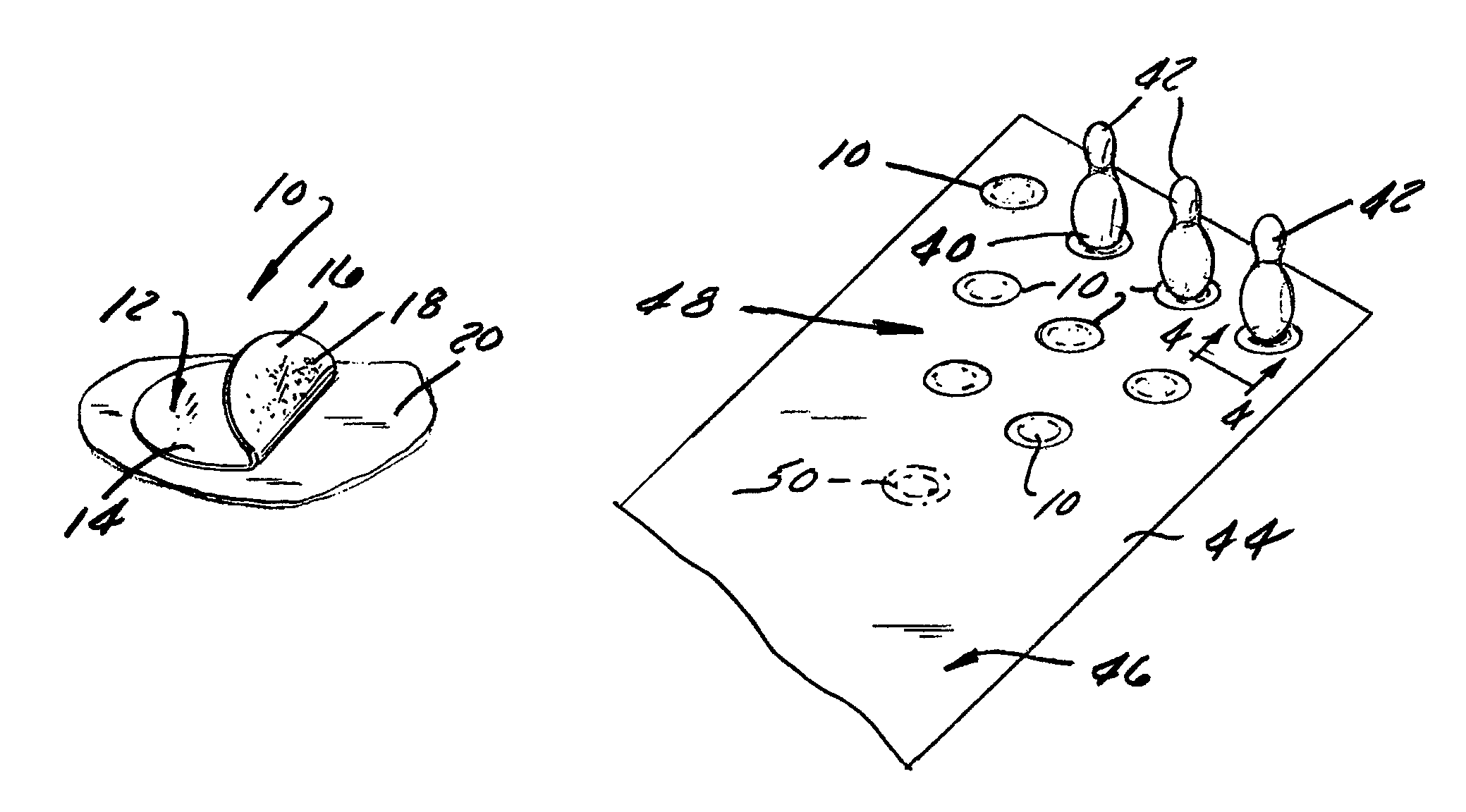
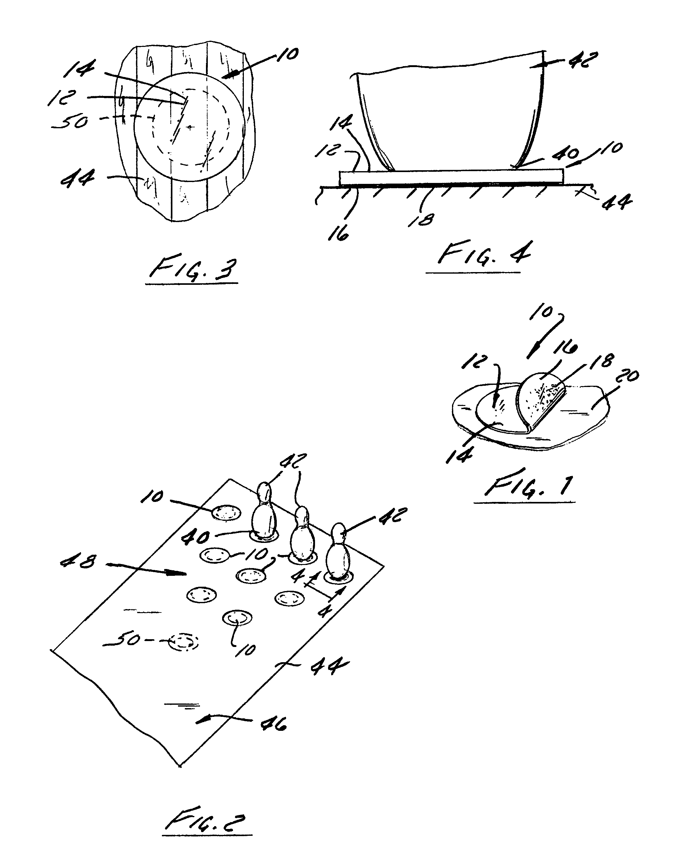
[0022]Referring to FIGS. 1 to 4, there is shown a preferred construction, application and function of a self-adhesive no-slide pin spot article constructed in accordance with an embodiment of the present invention. In FIG. 4, the thickness of the pin spot is exaggerated for clarity of illustration.

[0023]The no-slide pin spot, i.e., a bowling pin spotting article designated generally as 10, comprises a piece of frictional material 12 having a top, bowling pin-contacting surface 14 and a bottom surface 16, preferably having a pressure-sensitive adhesive 18 applied thereon. A release liner or backing 20, coated on one surface with a release agent (not shown), is provided so as to permit the pin spot 10 to be readily transported and stored yet easily peeled off of the backing 20 without disturbing the adhesive 18. It should be noted, however, that the pre-applied adhesive 18 and release backing 20 are not essential. An adhesive could instead be applied to the bottom surface 16 of the fr...


PUM


Abstract

An easily installed frictional bowling pin spot and a method of installing frictional pin spots on the pin deck of a bowling lane are disclosed. The preferred frictional pin spot is preferably a thin, circular polyurethane piece having a high coefficient of friction and packed with a pressure-sensitive adhesive. The pin spot increases the friction between a bowling pin and the pin deck thereby decreasing the likelihood of bowling pins hit by a ball or other pin sliding out of position instead of being knocked over.

Description

CROSS-REFERENCE TO RELATED APPLICATIONS[0001]This application claims priority under 35 U.S.C. §119 from U.S. Provisional Patent Application Ser. No. 60 / 827,339, filed on Sep. 28, 2006, and herein incorporated by reference in its entirety.BACKGROUND OF THE INVENTION[0002]1. Field of the Invention[0003]The invention relates to bowling lanes and, more particularly, to improvements in pin spots that are placed on a bowling lane pin deck.[0004]2. Discussion of the Related Art[0005]Until the middle of the twentieth century, bowling centers employed pin-boys, also known as pinsetters or pinspotters, to manually reset bowling pins in their correct position as indicated by pin spots, clear fallen pins and return bowling balls to the players. The bowling pins were something manually placed on pin spots, painted on the pin deck, that were slightly larger than the diameter of the bottom of the pins. The constant, repetitive placing of bowling pins on the pin spots caused them to wear unevenly i...

Claims


Application Information

Patent Timeline
Patent Type & Authority Patents(United States)
IPC IPC(8): A63D5/06
CPCA63D5/06
Inventor THORSON, SCOTT J.
Owner KEGEL LLC
Learn More