High bandwidth flexure for hard disk drives

Active Publication Date: 2011-08-23
MAGNECOMP
View PDF15 Cites 43 Cited by
  • Summary
  • Abstract
  • Description
  • Claims
  • Application Information

AI Technical Summary

Benefits of technology

[0018]In a first aspect, therefore, the invention is of a disk drive flexure including a bond pad disposed over a portion of the ground plane, the portion of the ground plane disposed vertically underneath the bond pad defining a bond pad ground plane area, the ground plane portion having a pattern of voids, where the pattern of voids improves imped

Problems solved by technology

However, the impedance of the flying leads has been relatively poorly matched to read-write head impedance because there is no ground plane under the flying leads.
As newer designs with lower and tighter impedance requirements are required to achieve higher flexure bandwidths, the impedance discontinuity within the flexure is becoming a larger issue.
Waveforms of circuits having fast switching speed are more susceptible to distortion from the signal line impedance than are waveforms of slower switching speed circuits.
Unfortunately, this standard technique generally cannot be used on the bond pad structures, because the pad size and pitch of the pads is controlled by the bonding technology.
These sizes are typically driven by hard drive manufacturer requirements and are not adjustable without greatly impacting the bonding process.
Unfortunately, the removal of such large sections of back plane results in a bond pad which is structurally similar to a flying lead.
The bond pad is less supported and thus less compatible with single sided bond pad processes.
The via holes allow increased support of the pads but are limited in how much they can alter impedance.

Method used


Image

  • High bandwidth flexure for hard disk drives
  • High bandwidth flexure for hard disk drives
  • High bandwidth flexure for hard disk drives

Examples


Embodiment Construction

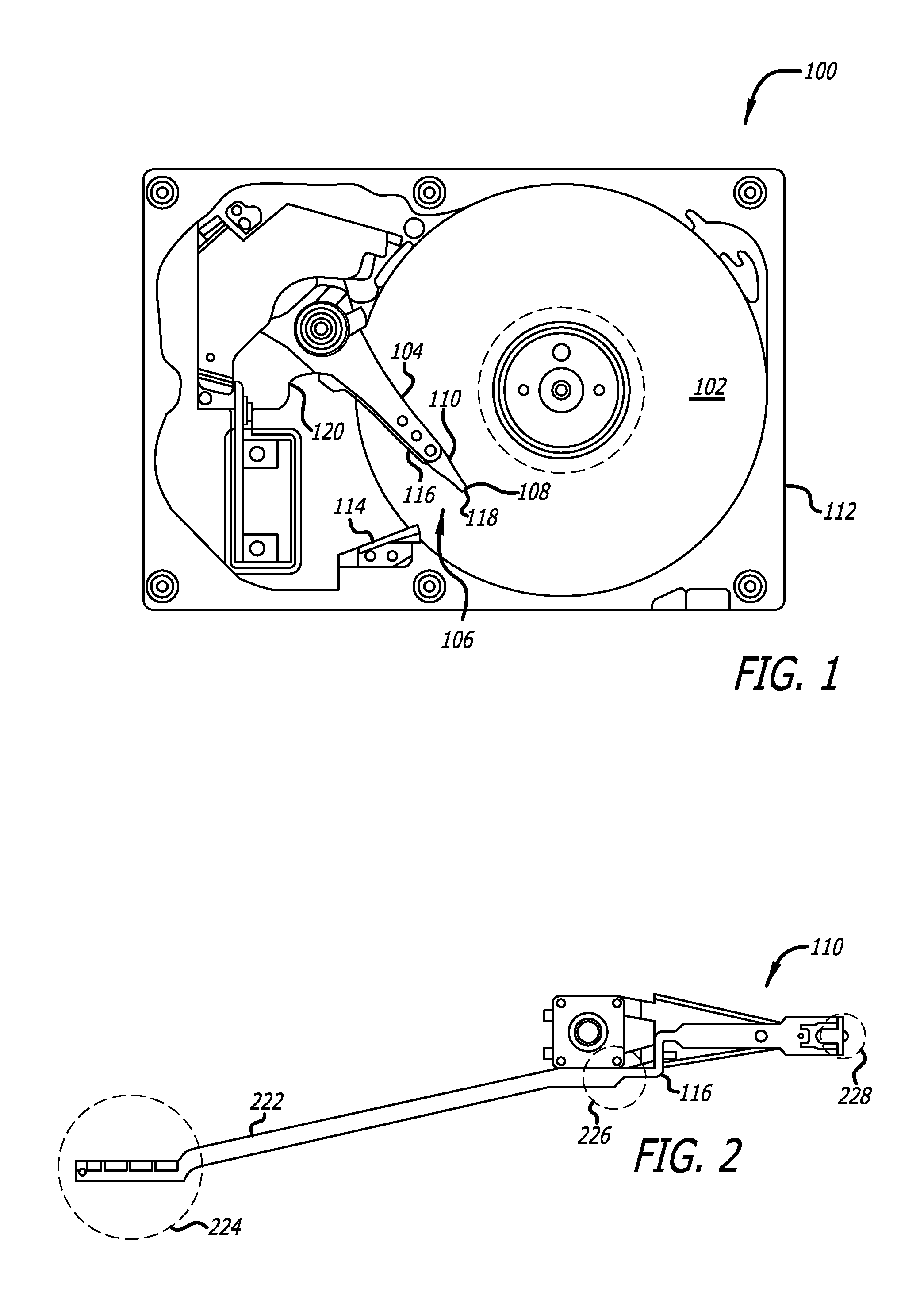
[0029]With reference to FIG. 1, a typical hard disk drive 100 includes at least one data storage disk 102 (e.g., one, two, three, or more disks), at least one actuator arm 104 (e.g., one, two, three, or more actuator arms), and at least one head suspension assembly (HSA) 106 (e.g., one, two, three, or more head suspension assemblies). Each HSA 106 is composed of a slider 108 and a suspension 110. FIG. 1 illustrates a state of hard drive 100 in which slider 108 is located for operation to access disk 102. Slider 108 is held by suspension 110 which in turn is supported by actuator arm 104. Actuator arm 104 is rotatably held to base 112 and typically rotated by a voice coil motor. A ramp 114 is disposed close to the outer circumference of disk 102 to have a withdrawal position to which slider 108 is unloaded from above the surface of disk 102 when rotation of disk 102 is stopped or in other situations. A tab 118 is formed at the distal end of suspension 110 and slides over a ramp 114 d...


PUM


Abstract

A disk drive flexure has a pattern of voids in the ground plane in the area directly underneath the read and write bond pads, in order to adjust the respective impedances of the read and write bond pad pairs to match the impedances of the read and write transducers and the signal trace pairs to and from the transducers. The resulting impedance matched bond pads increase the effective signal bandwidth of the flexure and its electrical connections, decreasing the probability of error at high signal speeds and increasing the maximum data rate through the suspension.

Description

CROSS-REFERENCE TO RELATED APPLICATIONS[0001]This application claims priority from U.S. Provisional Patent Application No. 61 / 040,895 filed Mar. 31, 2008.BACKGROUND OF THE INVENTION[0002]1. Field of the Invention[0003]This invention relates to the field of disk drives, and in particular to the field of high bandwidth flexures for hard disk drive drives.[0004]2. Description of Related Art[0005]A disk drive generally uses one or more spinning storage disks, sometimes called storage media, to store data. Disks can be rigid, as used in hard drives, or flexible, as used in floppy drives. Disks commonly store data using magnetic methods or optical methods, and can spin at rates exceeding 15,000 revolutions per minute (rpm). Hard disk drives generally employ several rigid disks stacked one on top of another with spaces in between, attached to a common spindle. Floppy disk drives generally employ a single flexible disk in a bonded sleeve.[0006]Over the surface of each disk in a disk drive, ...

Claims


Application Information

Patent Timeline
IPC IPC(8): G11B5/48
CPCG11B5/4833G11B5/486
Inventor DUNN, CHRISTOPHER GENE
Owner MAGNECOMP
Why Eureka
Try Eureka