Automatic configuration of synchronous block execution for control modules run in fieldbus networks

a fieldbus network and control module technology, applied in the field of process control systems, can solve the problems of limited bandwidth available, limited resources of data buses, and not all of the function blocks of a particular control module can be executed in the actual, and achieve the effect of faster rate and convenient and more optimal us

Active Publication Date: 2011-08-23
FISHER-ROSEMOUNT SYST INC
View PDF24 Cites 6 Cited by
  • Summary
  • Abstract
  • Description
  • Claims
  • Application Information

AI Technical Summary

Benefits of technology

Additionally, an apparatus or method automatically configures a control module for synchronous execution on a Fieldbus segment by determining if all of the critical function blocks of a particular control module can be assigned to FOUNDATION® Fieldbus field devices or to the I / O device associated with a particular Fieldbus segment. If so, the apparatus or method automatically assigns the function blocks of the control module, which would otherwise be scheduled to execute in a controller, to the I / O device for the Fieldbus segment. This technique thereby enables all of the function blocks within the control module (or at least all of the critical or necessary function blocks within the control module) to execute in one macrocycle of the Fieldbus segment, thereby executing synchronously on a Fieldbus segment. This operation, in turn, increases the overall execution rate of the control module. In other words, the disclosed apparatus and method enable the function blocks of a control module including, for example, control function blocks, to be executed and to communicate with one another over a Fieldbus segment within a single scheduled macrocycle of the Fieldbus segment, thereby enabling faster operation of the control module over control modules that have function blocks split between a controller and field devices on a Fieldbus segment.
The automatic assignment of function blocks to devices on the Fieldbus segment and the automatic generation of the communication and execution schedule on the Fieldbus segment allows the operator or configuration engineer to simply specify the control loops (control modules) to be executed on a particular Fieldbus segment without having to worry about where to assign the function blocks, or the best schedule to use when configuring the Fieldbus segment. This operation thereby enables easier and more optimal use of the process control system assets while simultaneously configuring the control modules to execute at a faster rate, where possible, by placing as many of the function blocks associated with a particular control module into an I / O device on a Fieldbus segment.

Problems solved by technology

However, these data buses have limited resources including limited bandwidth available for field devices and process controllers to communicate information to one another.
Unfortunately, in many cases, not all of the function blocks making up a particular control module could be executed in the actual field devices connected to a Fieldbus segment, as many of the function blocks were simply not supported by the particular field devices connected to the Fieldbus segment.
Thus, unfortunately, a control module having function blocks disposed in both the FF field devices and a controller cannot generally execute in a single macrocycle defined by the Fieldbus segment schedule, but instead has to operate over a series of macrocycles of the Fieldbus segment schedule to allow for proper communications between the controller and the FF field devices through the input / output device.
Splitting the blocks in this manner introduces significant delay into the control loop, because the execution of the blocks in the controller is not synchronized with the execution of the blocks on the Fieldbus segment.

Method used


Image

  • Automatic configuration of synchronous block execution for control modules run in fieldbus networks
  • Automatic configuration of synchronous block execution for control modules run in fieldbus networks
  • Automatic configuration of synchronous block execution for control modules run in fieldbus networks

Examples


Embodiment Construction

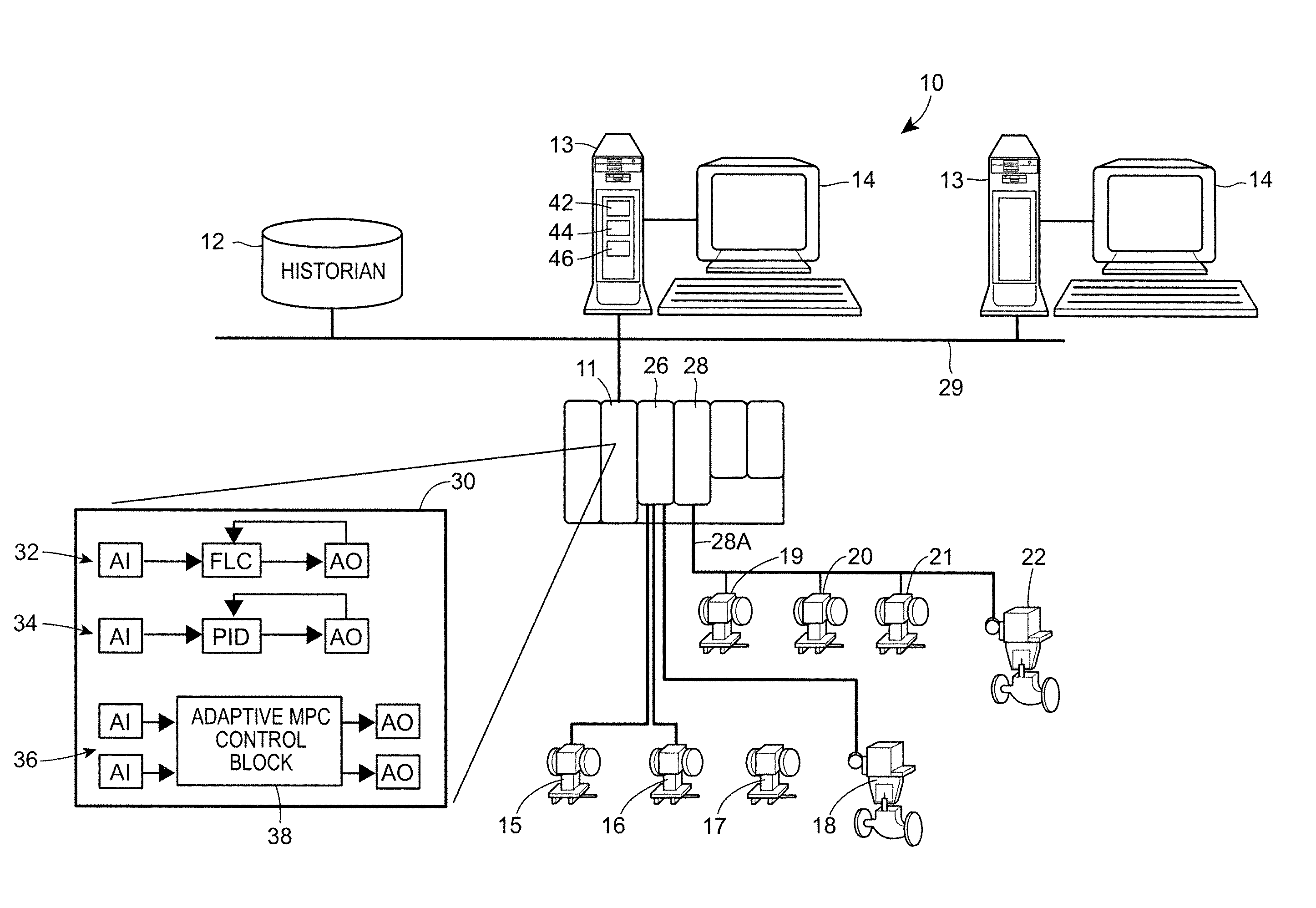
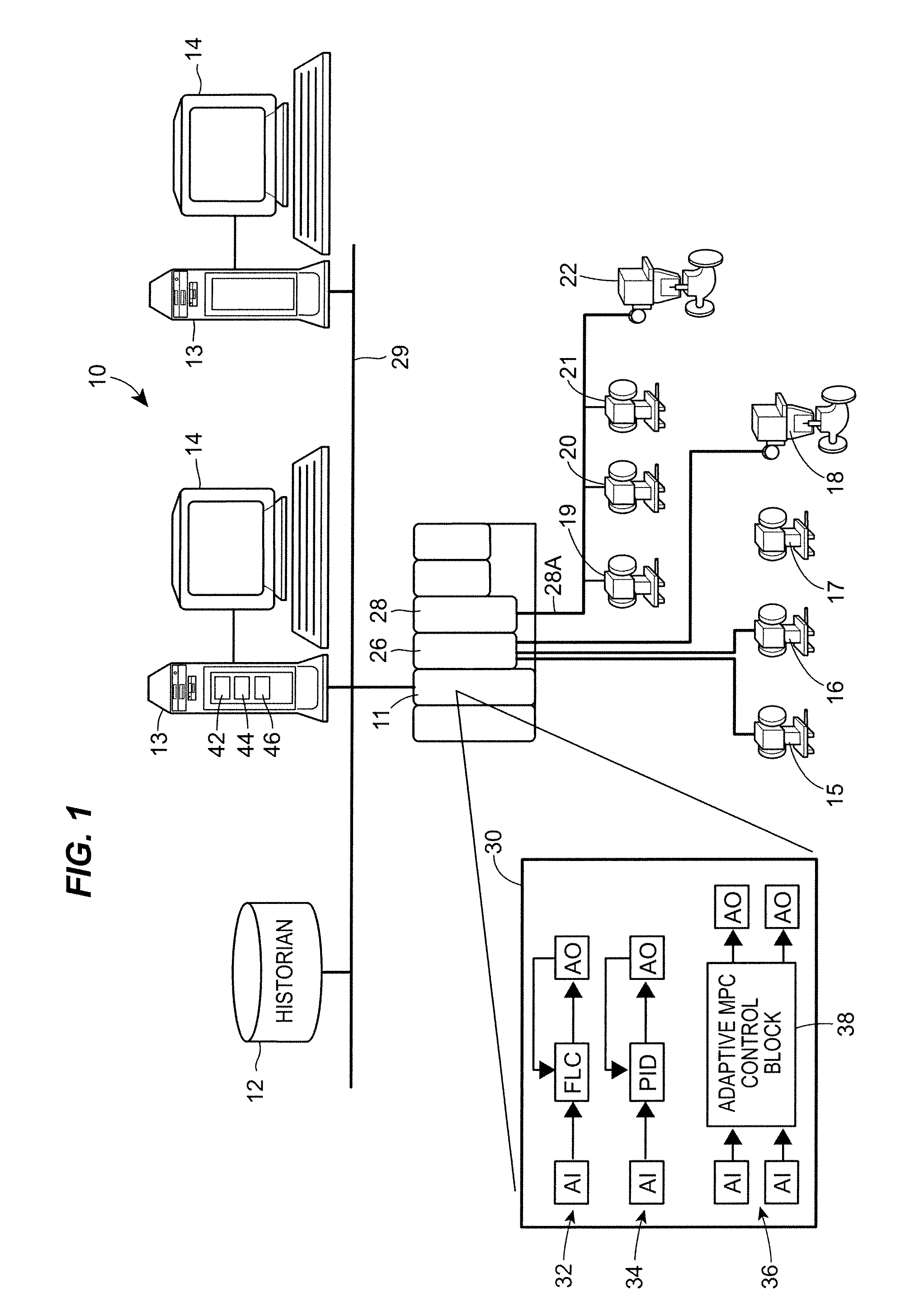
Referring now to FIG. 1, a process control system 10 includes a process controller 11 communicatively connected to a data historian 12 and to one or more host workstations or computers 13 (which may be any type of personal computers, workstations, etc.) each having a display screen 14. The controller 11 is also connected to field devices 15-22 via input / output (I / O) devices or cards 26 and 28. The data historian 12 may be any desired type of data collection unit having any desired type of memory and any desired or known software, hardware or firmware for storing data and may be separate from (as illustrated in FIG. 1) or a part of one of the workstations 13. The controller 11, which may be, by way of example, the DeltaV™ controller sold by Emerson Process Management is communicatively connected to the host computers 13 and the data historian 12 via, for example, an Ethernet communication link or any other desired communication network 29. The communication network 29 may be in the f...


PUM


Abstract

A method or apparatus automatically configures a control module for synchronous execution on a Fieldbus segment of a process control network by determining if all of the critical function blocks of a particular control module can be assigned to FOUNDATION® Fieldbus field devices or to the I / O device associated with a particular Fieldbus segment. If so, the method or apparatus automatically assigns the function blocks of the control module, which would otherwise be scheduled to execute in a controller, to the I / O device for the Fieldbus segment. This technique enables all of the critical or necessary function blocks within the control module to execute in one macrocycle of the Fieldbus segment, thereby executing synchronously on a Fieldbus segment. This operation, in turn, increases the overall execution rate of the control module with respect to control modules that have function blocks split between a controller and field devices on a Fieldbus segment, which has been the traditional manner of configuring control modules implemented using devices on a Fieldbus segment.

Description

FIELD OF THE DISCLOSUREThis patent relates generally to process control systems and, more particularly, to a system that assigns various function blocks of a control module to an input / output card on a Fieldbus segment, and that generates schedules to execute the function blocks of the control module synchronously within the Fieldbus segment.BACKGROUNDProcess control systems, like those used in chemical, petroleum or other processes, typically include one or more centralized process controllers communicatively coupled to at least one host or operator workstation and to one or more field devices via analog, digital or combined analog / digital buses. The field devices, which may be, for example, valves, valve positioners, switches, transmitters (e.g., temperature, pressure and flow rate sensors), etc. perform functions within the process such as opening or closing valves and measuring process parameters. The process controller receives signals indicative of process measurements made by...

Claims


Application Information

Patent Timeline
Patent Type & Authority Patents(United States)
IPC IPC(8): G05B11/01
CPCG05B19/042G05B19/4185G05B2219/1134G05B2219/32248G05B2219/25232G05B2219/31121G05B2219/25229Y02P90/02G05B19/0423
Inventor ENVER, ALPER T.KRIVOSHEIN, KENNETH D.CHRISTENSEN, DANIEL D.RAMACHANDRAN, RAMLUCAS, JOHN M.TANYOUS, EBTESAM S.
Owner FISHER-ROSEMOUNT SYST INC
Why Eureka
Try Eureka