Diffusers, diffusion systems, and methods for controlling airflow through diffusion systems

a diffusion system and diffuser technology, applied in the direction of machines/engines, liquid fuel engines, stators, etc., can solve the problems of airflow around, diffusers and engines not operating as efficiently as desired

Inactive Publication Date: 2011-08-30
HONEYWELL INT INC
View PDF14 Cites 28 Cited by
  • Summary
  • Abstract
  • Description
  • Claims
  • Application Information

AI Technical Summary

Problems solved by technology

However, the smaller curvature radius may cause airflow around the curved section to have a tendency to separate from the inner wall and to flow toward the outer wall.
As a result, the diffuser and engine may not operate as efficiently as desired.

Method used


Image

  • Diffusers, diffusion systems, and methods for controlling airflow through diffusion systems
  • Diffusers, diffusion systems, and methods for controlling airflow through diffusion systems
  • Diffusers, diffusion systems, and methods for controlling airflow through diffusion systems

Examples


Embodiment Construction

The following detailed description is merely exemplary in nature and is not intended to limit the inventive subject matter or the application and uses of the inventive subject matter. Furthermore, there is no intention to be bound by any theory presented in the preceding background or the following detailed description. Although the inventive subject matter is, for convenience of explanation, depicted and described as being implemented in a turbofan gas turbine jet engine, it will be appreciated that it can be implemented in various other types of turbines, such as turboshaft engines, and in various other systems and environments.

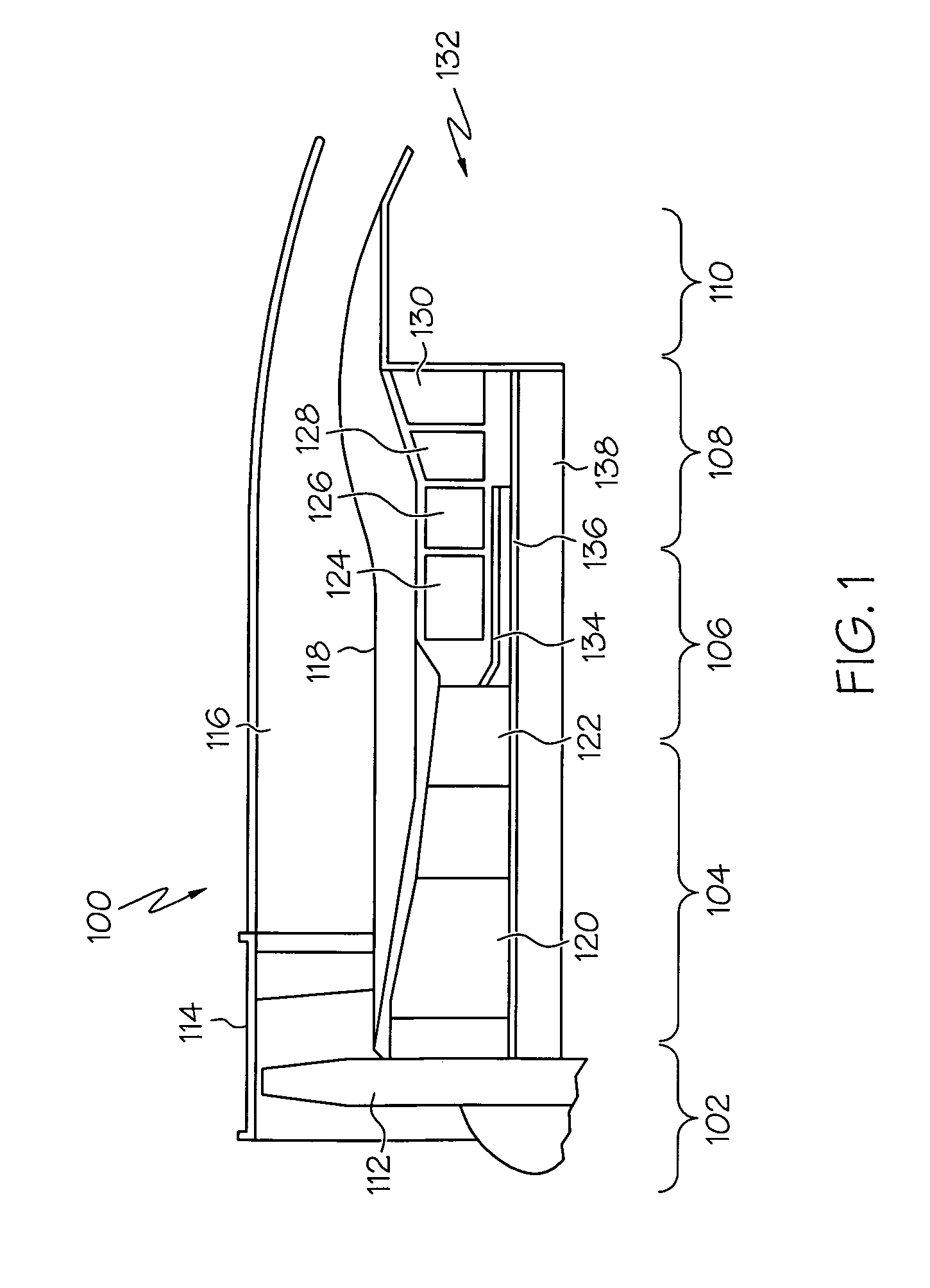
FIG. 1 is a simplified, schematic of a gas turbine engine 100, according to an embodiment. The gas turbine engine 100 generally includes an intake section 102, a compressor section 104, a combustion section 106, a turbine section 108, and an exhaust section 110. The intake section 102 includes a fan 112, which is mounted in a fan case 114. The fan 112 draws...


PUM


Abstract

A diffuser is provided that includes a first wall, a second wall, and a first plasma actuator. The first wall has a radially-extending section and a curved section. The second wall has a radially-extending section and a curved section that are spaced apart from the radially-extending section and the curved section of the first wall such that the curved section of the second wall is disposed radially inwardly from the curved section of the first wall and a flow path is defined therebetween. The first plasma actuator is disposed on the curved section of the second wall, and the first plasma actuator is adapted to generate a first electric field to ionize a first portion of air flowing along the flow path to form a plurality of ionized species capable of inducing a second portion of air to flow in a desired direction.

Description

TECHNICAL FIELDThe inventive subject matter generally relates to engines, and more particularly relates to diffusers and diffusion systems for use in engines, and methods for controlling airflow through engine diffusion systems.BACKGROUNDA turbofan gas turbine engine may be used to power aircraft and may include, for example, a fan section, a compressor section, a combustion section, a turbine section, and an exhaust section. The fan section induces air from the surrounding environment into the engine and accelerates a fraction of the air toward the compressor section. The remaining fraction of air is accelerated into and through a bypass plenum, and out the exhaust section.The compressor section, which may include a high pressure compressor and a low pressure compressor, raises the pressure of the air it receives from the fan section to a relatively high level. The compressed air then enters the combustion section, where a ring of fuel nozzles injects a steady stream of fuel into a...

Claims


Application Information

Patent Timeline
Patent Type & Authority Patents(United States)
IPC IPC(8): F02C1/00
CPCF01D9/02F02C3/08F15D1/06F15D1/14F05D2270/172F05D2250/52F04D29/441F04D29/687
Inventor NOLCHEFF, NICKFRIAS, DAN
Owner HONEYWELL INT INC
Why Eureka
Try Eureka