Method and Apparatus for Measuring Thrust

a technology of thrust measurement and method, applied in the field of space propulsion, can solve the problems of controlling the spread of calibration data, multiple sources of errors, etc., and achieve the effect of reducing nois

Active Publication Date: 2016-07-14
UNIV OF FLORIDA RES FOUNDATION INC
View PDF0 Cites 21 Cited by
  • Summary
  • Abstract
  • Description
  • Claims
  • Application Information

AI Technical Summary

Problems solved by technology

The advent of nanosatellites has given rise to a new challenge in the field of space propulsion.
The following error analysis shows that this electrostatic method inherently introduces multiple sources of error, necessitating a better calibration method.
However, the electrode gap L (typically 1 mm), and the sensor resolution dx (5 nm as per manufacturer specifications at www.philtec.com, LDS Model D100) present the biggest challenge in controlling the spread of the calibration data.

Method used


Image

  • Method and Apparatus for Measuring Thrust
  • Method and Apparatus for Measuring Thrust
  • Method and Apparatus for Measuring Thrust

Examples


Embodiment Construction

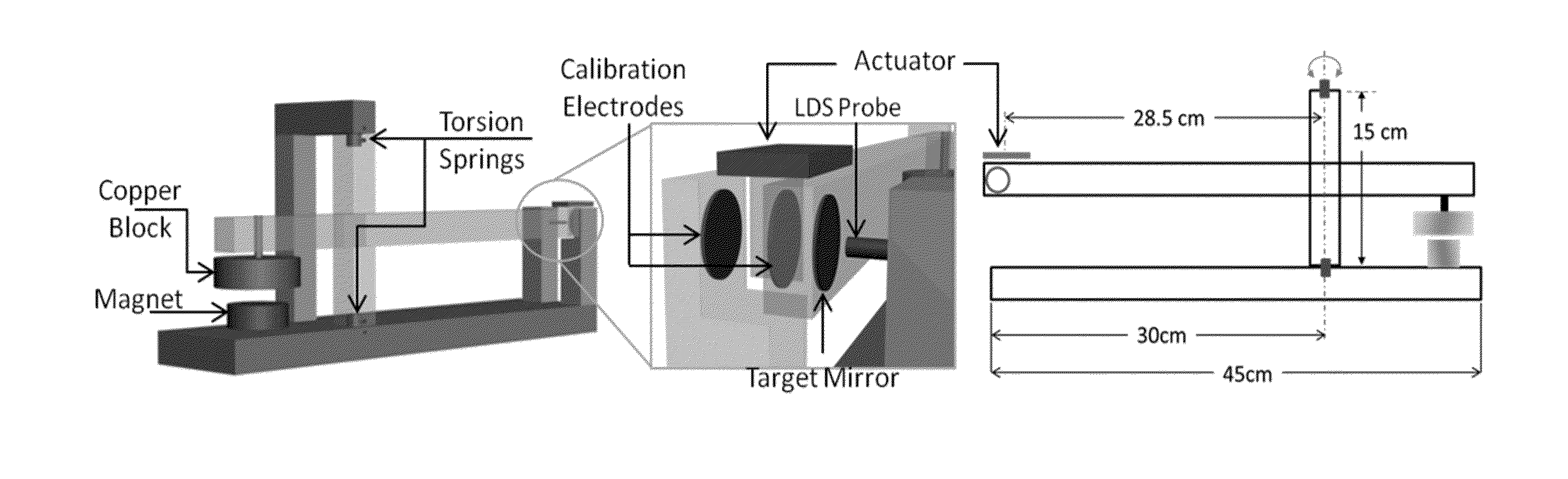
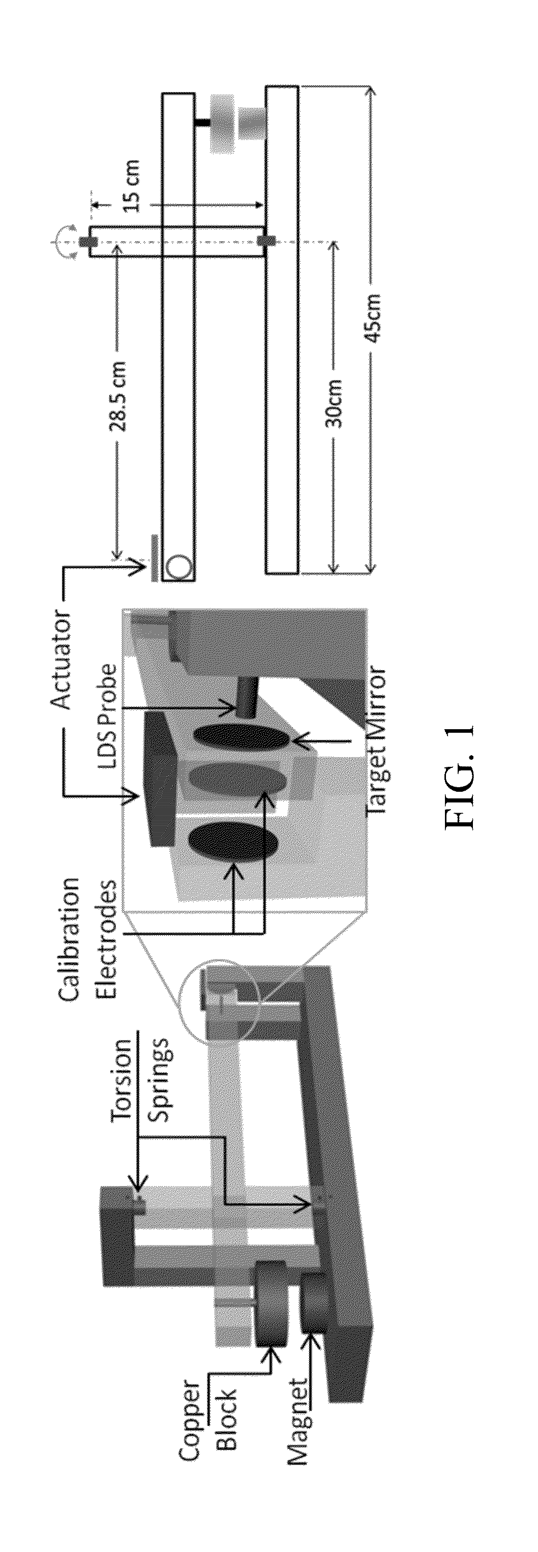
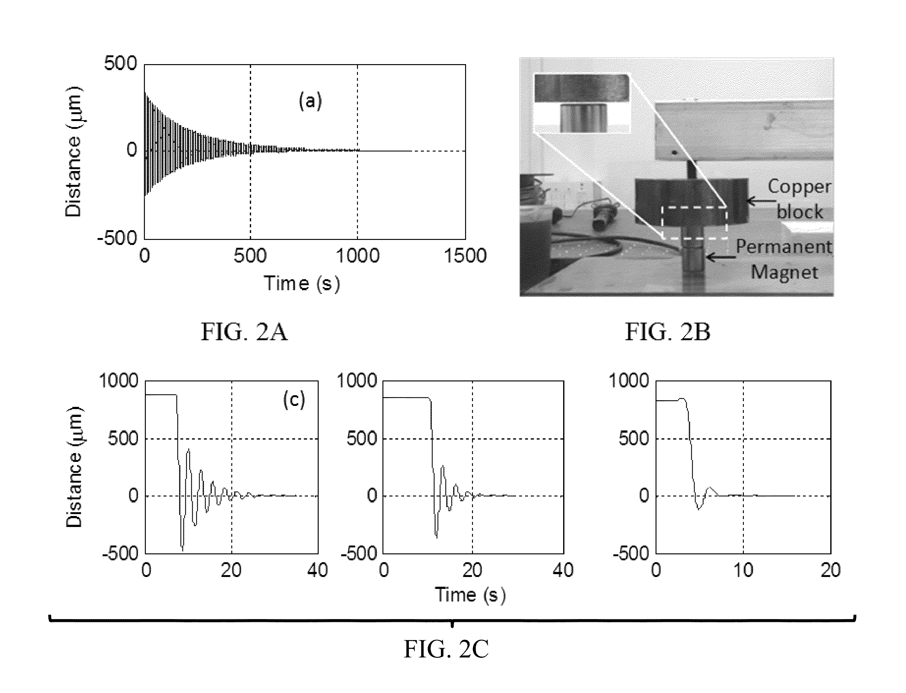
[0023]Embodiments of the invention relate to a thrust stand and a method of measuring thrust. Specific embodiments have a resolution less than 100 nN, less than 90 nN, less than 80 nN, less than 70 nN, less than 60 nN, less than 50 nN, less than 40 nN, less than 30 nN, less than 20 nN, and / or less than 10 nN. Embodiments of the invention pertain to a method of calibrating a thrust stand. Embodiments of the subject thrust stand can incorporate a passive eddy current based damper. Specific embodiments of the passive eddy current based damper can function without contact with the balance arm. Further specific embodiments of the passive eddy current based damper can be used in a vacuum. Embodiments can utilize signal analysis techniques to identify and reduce noise. A logarithmic decrement method can be used to calibrate the thrust stand. Calibrated system noise floor results indicate a thrust measurement resolution in the range 10-20 nN can be achieved under laboratory conditions. Inte...


PUM

PropertyMeasurementUnit
pressureaaaaaaaaaa
pressureaaaaaaaaaa
thrustaaaaaaaaaa

Abstract

Embodiments of the invention relate to a thrust stand and a method of measuring thrust. Embodiments of the invention pertain to a method of calibrating a thrust stand. Embodiments of the subject thrust stand can incorporate a passive eddy current based damper. Specific embodiments of the passive eddy current based damper can function without contact with the balance arm. Further specific embodiments of the passive eddy current based damper can be used in a vacuum. Embodiments can utilize signal analysis techniques to identify and reduce noise. A logarithmic decrement method can be used to calibrate the thrust stand. Force measurements can be made with embodiments of the subject thrust stand for a standard macroscale dielectric barrier discharge (DBD) plasma actuator and / or other thrust producing devices.

Description

CROSS-REFERENCE TO RELATED APPLICATION[0001]The present application claims the benefit of U.S. Provisional Patent Application Ser. No. 61 / 870,132, filed Aug. 26, 2013, which is hereby incorporated by reference herein in its entirety, including any figures, tables, or drawings.BACKGROUND OF THE INVENTION[0002]The advent of nanosatellites has given rise to a new challenge in the field of space propulsion. These satellites, typically weighing between 1 and 10 kg, require very minute forces for executing maneuvers for station keeping, orbital corrections, and attitude control. These forces are often of the order of a few micronewtons or less. Although the design for thrusters capable of delivering these forces has been around for some time [1], the need exists for a simple, low cost measurement method that resolves these sub-micro-Newton forces accurately and reliably.[0003]Thrust stands, which use the principle of a torsion balance, were conceived by Charles Coulomb to measure the elec...

Claims


Application Information

Patent Timeline
Patent Type & Authority Applications(United States)
IPC IPC(8): G01L1/08G01H1/10G01L25/00
CPCG01L1/086G01H1/10G01L25/00G01L5/133
Inventor ROY, SUBRATASONI, JIGNESH
Owner UNIV OF FLORIDA RES FOUNDATION INC
Why Eureka
Try Eureka