Plasma cooling heat sink

a technology of heat sink and plasma, which is applied in the direction of heat transfer modification, indirect heat exchanger, lighting and heating apparatus, etc., can solve the problems of reducing the lifespan of these devices, consuming higher electricity for cooling, and generating significant heat for electronic devices

Inactive Publication Date: 2008-12-11
OUYANG CHIEN
View PDF13 Cites 22 Cited by
  • Summary
  • Abstract
  • Description
  • Claims
  • Application Information

AI Technical Summary

Benefits of technology

[0012]One embodiment of the present invention provides a plasma-driven cooling device couple to heat sink fins to induce the gas flow along the heat sink fins. The induced gas flow will remove the heat away from heat sink fin surface and therefore the heat source is cool down.

Problems solved by technology

Electronic devices may generate significant heat during operation.
High temperatures may reduce the lifespan of these devices, and, therefore, the generated heat may need to be dispersed to keep the operating temperature of the electronic devices within acceptable limits.
However, when the pitch becomes very small, the pressure drop between inlet and outlet of the heat sink fins may become very high, which may results the difficulties to pump the fluid flowing through fins, and as a result, more powerful fans, which consume higher electricity may be needed for the cooling.
Another consideration of the electronic device cooling is that, due to size concern, the internal space allowed to put cooling fans and other cooling components, may be limited or not permitted.
However, none of the above patents are coupled to the heat sink, which is a fundamental apparatus for cooling electronic devices.

Method used


Image

  • Plasma cooling heat sink
  • Plasma cooling heat sink
  • Plasma cooling heat sink

Examples


Embodiment Construction

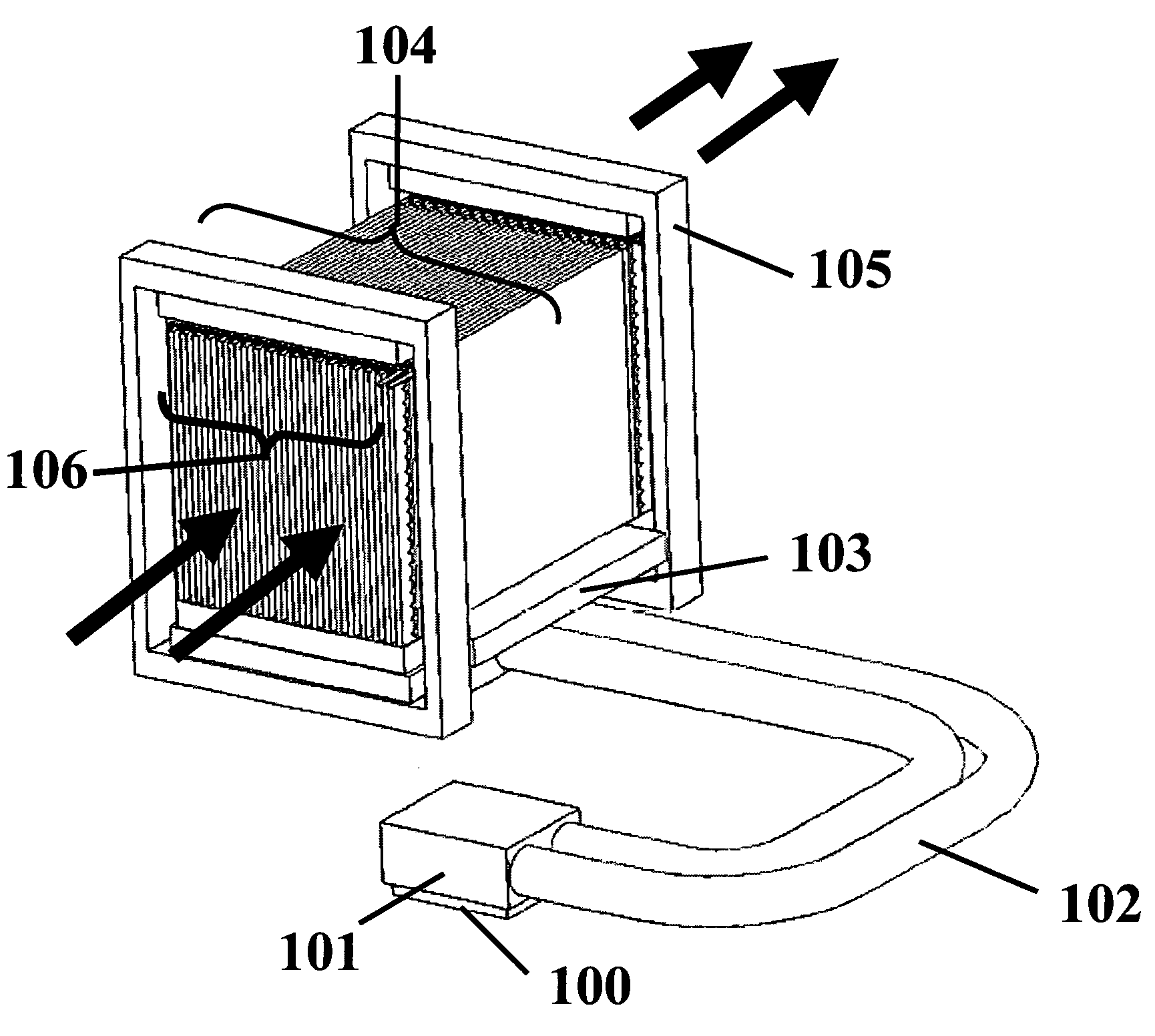
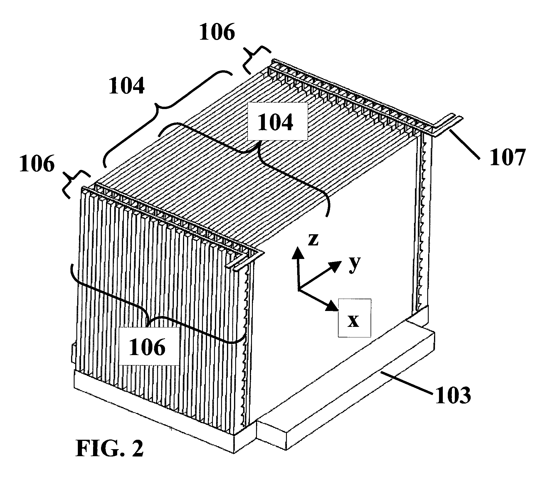
[0036]The invention generally relates to apparatus for cooling microelectronic devices or packages, such as microprocessors, and ASIC. Such systems and methods may be used in a variety of applications. A non-exhaustive list of such applications includes the cooling of: a microprocessor chip, a graphics processor chip, an ASIC chip, a video processor chip, a DSP chip, a memory chip, a hard disk drive, a graphic card, a portable testing electronics, a personal computer system.

[0037]Take laptop computer for example, conventional fans use a lot of space and energy. For this reason, the plasma-driven cooling device represents a way to increase their cooling capacity and make them more reliable and far quieter. Therefore the higher-performance chips that generate too much heat for current laptops can be used.

[0038]As used herein “plasma” is an ionized gas, a gas into which sufficient energy is provided to free electrons from atoms or molecules and to allow both species, ions and electrons...


PUM


Abstract

One embodiment of the present invention uses plasma-driven gas flow to cool down electronic devices. The cooling device comprises heat sink fin assembly, plasma actuator assembly, and magnetic circuit assembly. The plasma actuator assembly comprises electrodes and dielectric pieces. Voltages are applied to electrodes to drive the plasma gas flow. The magnetic circuit assembly provides magnetic field to interact with electrical field and plasma flow, and therefore an induced gas flow is pumped into, or pumped out from, heat sink fin assembly, to cool down heat sink fins.

Description

[0001]This application is a Formal Application and claims priority to pending U.S. patent application 60 / 934,047 filed on Jun. 9, 2007 by the same Applicant of this Application, the benefit of its filing date being hereby claimed under Title 35 of the United States Code.BACKGROUND OF THE INVENTION[0002]1. Field of the Invention[0003]The present invention relates generally to electronic equipment, and more particularly, to apparatus and methods for cooling electronic devices using plasma-driven gas flow.[0004]2. Description of the Related Art[0005]Electronic devices may generate significant heat during operation. High temperatures may reduce the lifespan of these devices, and, therefore, the generated heat may need to be dispersed to keep the operating temperature of the electronic devices within acceptable limits.[0006]One commonly used cooling device is heat sink. Heat sinks may be coupled to electronic devices to absorb heat through the heat sink base and disperse the heat through...

Claims


Application Information

Patent Timeline
Patent Type & Authority Applications(United States)
IPC IPC(8): F28D15/00
CPCF28F13/16
Inventor OUYANG, CHIEN
Owner OUYANG CHIEN
Why Eureka
Try Eureka