Methods and apparatus for reducing drag via a plasma actuator

a plasma actuator and actuator technology, applied in the direction of air-flow influencers, machines/engines, roofs, etc., can solve the problems of small improvement in fuel consumption, slow fleet acceptance, and/or insufficient structural sound to handl

Active Publication Date: 2012-01-10
UNIV OF NOTRE DAME DU LAC
View PDF37 Cites 24 Cited by
  • Summary
  • Abstract
  • Description
  • Claims
  • Application Information

AI Technical Summary

Problems solved by technology

Previous efforts to reduce the drag of these rigs have made some improvements, but so far have been slow to gain acceptance into the fleets because they interfere with the utility of the vehicle, require extensive power, are expensive modifications, show small improvements in fuel consumption and / or are not structurally sound enough to handle the day-to-day rough conditions that these vehicles experience.

Method used


Image

  • Methods and apparatus for reducing drag via a plasma actuator
  • Methods and apparatus for reducing drag via a plasma actuator
  • Methods and apparatus for reducing drag via a plasma actuator

Examples


Embodiment Construction

[0037]The following description of various examples is not intended to limit the scope of the invention to the precise form or forms detailed herein. Instead, the following description is intended to be illustrative of the principles of the disclosure so that others may follow its teachings.

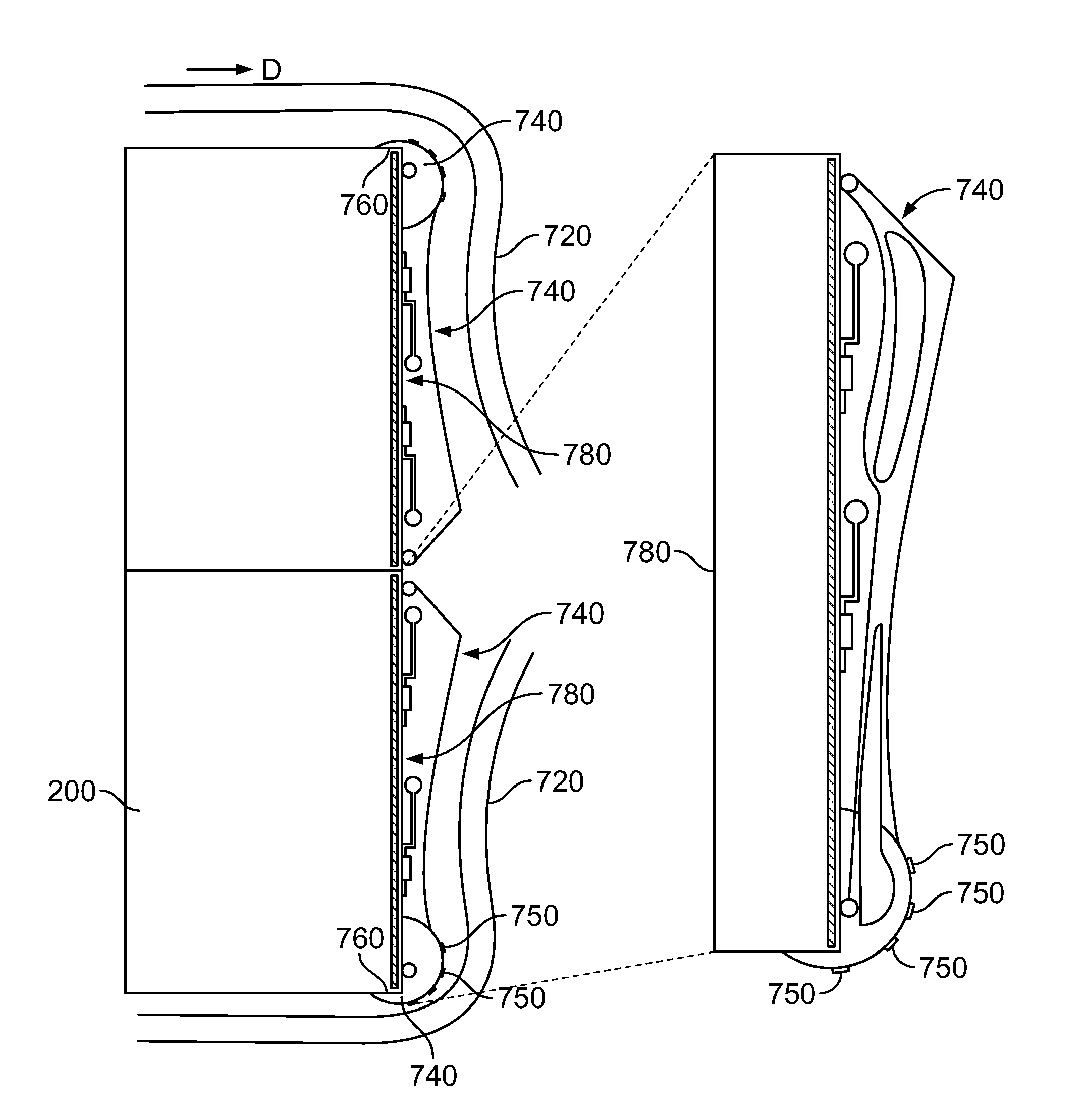
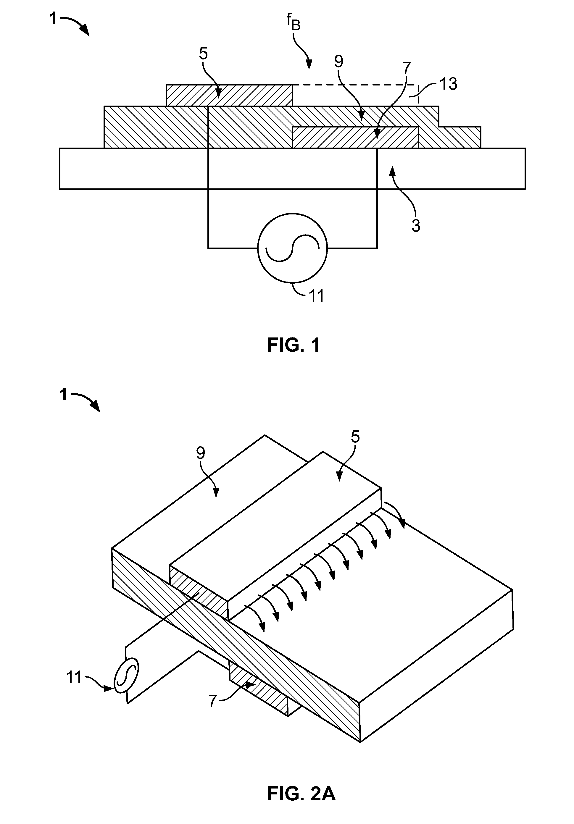
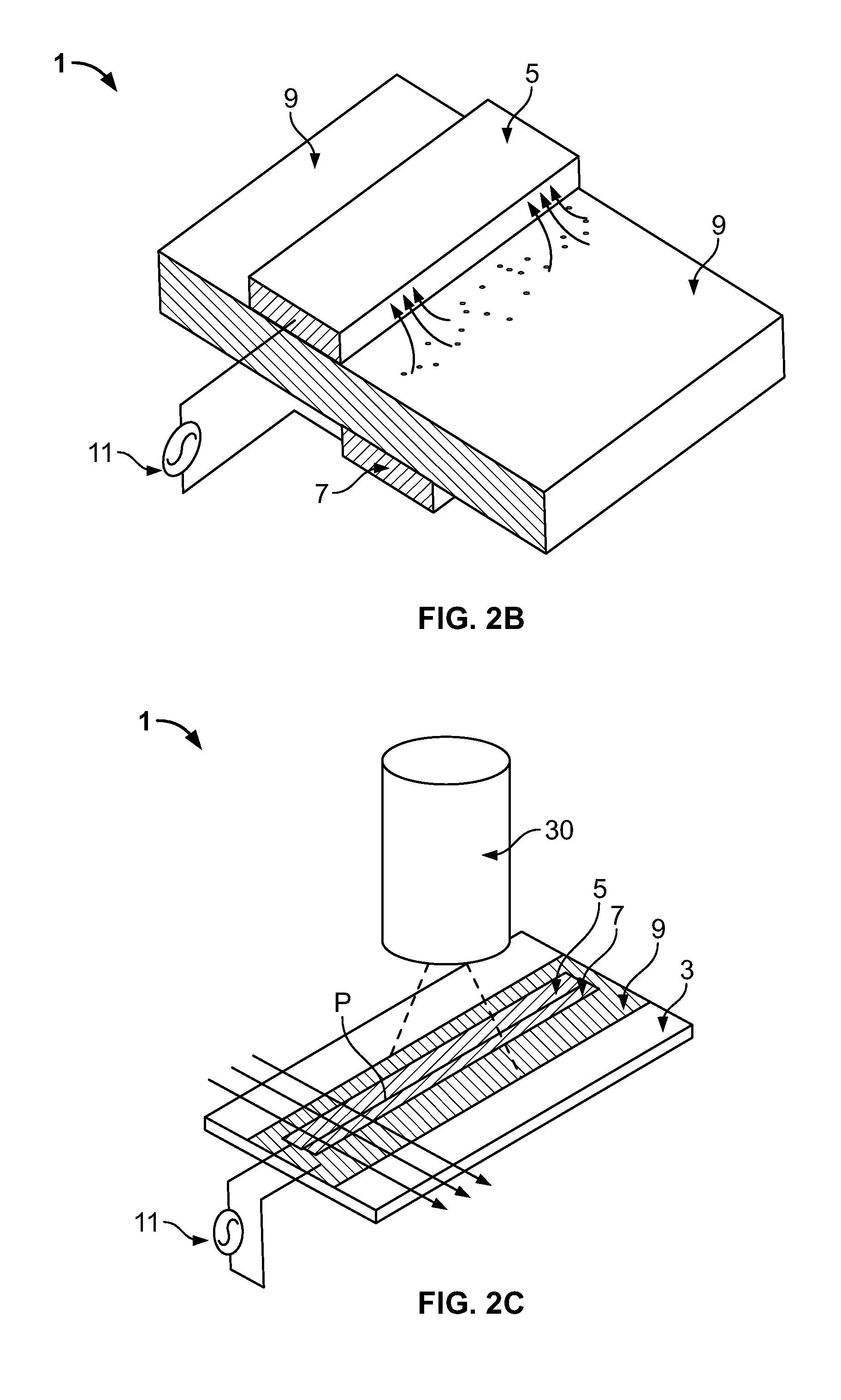
[0038]Referring to FIG. 1, an example single-dielectric barrier discharge (SDBD) plasma actuator 1 is attached to a surface 3, such as a fairing and / or a vehicle as will be described below. The actuator 1 may be attached to the surface such as, in particular, any region in which airflow separates from the surface 3. The example plasma actuator 1 includes an exposed electrode 5, a covered, insulated electrode 7 and a dielectric barrier material 9. The exposed electrode 5 may be at least partially covered, while the insulated electrode 7 may be at least partially exposed. In this example, an alternating current (AC) voltage source 11 is electrically coupled to the electrodes 5 and 7.

[0039]Although ...


PUM


Abstract

A vehicle includes a surface over which airflow passes. A plasma actuator is configured to generate plasma above the surface, the plasma coupling a directed momentum into the air surrounding the surface to reduce separation of the airflow from the surface. A method of reducing separation of airflow from a surface of the vehicle includes generating plasma in air surrounding the surface at a position where the airflow would separate from the surface in the absence of the plasma.

Description

CROSS REFERENCE TO RELATED APPLICATION[0001]This application is a non-provisional application claiming priority from U.S. Provisional Application Ser. No. 60 / 856,871, filed Nov. 2, 2006, entitled “Truck Tractor and Trailer Aerodynamic Drag Reduction Using Single Dielectric Barrier Discharge (SDBD) Plasma Actuators” and incorporated herein by reference in its entirety.FIELD OF THE DISCLOSURE[0002]The present disclosure relates generally to drag reduction, and more particularly, to methods and apparatus for reducing drag via a plasma actuator.BACKGROUND OF RELATED ART[0003]Trucks, such as for example, class-8 heavy duty trucks typically use significant amounts of fuel to move cargo across the nation. In most instances, very little attention has been paid to the major drag-producing design with the exception of a passive fairing placed over the tractor top and / or side to help close the gap between tractor and trailer. Separated flow typically exists over many of the surfaces to include...

Claims


Application Information

Patent Timeline
Patent Type & Authority Patents(United States)
IPC IPC(8): B62D35/00
CPCB62D35/00B62D35/001B64C23/005F05D2270/172Y02T50/166B64C2230/12Y02T50/10H05H1/2439
Inventor CORKE, THOMAS C.SPIVEY, RICHARD
Owner UNIV OF NOTRE DAME DU LAC
Why Eureka
Try Eureka