Pressure exchanger

a technology of pressure exchanger and pressure exchanger, which is applied in the direction of combination engines, machines/engines, liquid fuel engines, etc., can solve the problems of limiting the unit flow capacity of the unit, affecting the flow rate of the unit, and requiring extreme and costly tolerances in the manufacturing of certain parts, so as to improve the flow rate and reduce the risk of cavitation. , the effect of increasing the flow capacity

Active Publication Date: 2007-12-11
ISOBARIC STRATEGIES INC
View PDF13 Cites 70 Cited by
  • Summary
  • Abstract
  • Description
  • Claims
  • Application Information

AI Technical Summary

Benefits of technology

[0009]In accordance with at least one embodiment of this invention, a pressure exchanger having increased flow capacity and start momentum is provided. The pressure exchanger according to this embodiment utilizes the one-side unidirectional impulse momentum principle for self-rotation that is less susceptible to cavitation.
[0010]In accordance with at least one embodiment of this invention, a pressure exchanger is configured to exhibit increased flow capacity along with improved operational and manufacturing efficiency. The pressure exchanger according to this embodiment comprises a center axle for rotor positioning along with a full diameter sized rotor.
[0011]In accordance with at least one embodiment of this invention a pressure exchanger having improved depressurization and pressurization of rotor ducts is provided. The pressure exchanger according to this embodiment comprises a geometry controlled decrease of end cover clearance in the direction of rotation for achieving this improved performance.
[0012]In accordance with at least one embodiment of this invention, a pressure exchanger is configured to be less susceptible to substantial or asymmetric deformation of the end cover axle is provided. By complete force balancing through an area exposed to high pressure positioned substantially opposite to the centroid of the separation force of each end-cover. The pressure exchanger according to this embodiment is able to achieve equivalent or improved performance and allow the use of materials other than ceramics and a larger length / diameter ratio for the rotor.

Problems solved by technology

Commercial pressure exchangers of the above-mentioned category are known to exhibit operational flow limitations due to excessive noise, flow resistance, intermixing and cavitation despite the application of above mentioned patents.
Furthermore, the manufacturing of certain parts requires extreme and costly tolerances and limited choice of materials due to asymmetric elastic deformations.
The trailing section of the rotor duct exposed to the exit flow of the low-pressure fluid is under cavitation risk at high flow velocities and therefore a limiting factor for unit flow capacity.
U.S. Pat. No. 5,988,993 to Hauge, hereby incorporated by reference in its entirety, describes a positioning system of a rotor that requires extremely tight tolerances for the mating of the rotor and the outer bearing sleeve, which makes manufacturing costly.
Furthermore, the hydrostatic bearing principle requires high degree of filtration as fluid is bled from the fluid stream under high pressure and passed through the radial rotor / sleeve clearances in a dead-end mode.
This may cause silting and blockage of rotor under certain circumstances and applications.
The outer sleeve also prevents rotor OD from being sized according to end cover OD or pressure vessel ID, and therefore limits efficiency and capacity further.
However, in reality it is only partially successful as cavitation damage is moved to the connecting channel and away from the exit edge of the end cover port.
U.S. Pat. No. 6,659,731 to Hauge, hereby incorporated by reference in its entirety, describes returning depressurized fluid through the center of the rotor to induce unnecessary flow resistance with lower efficiency resulting.
The pressure vessel described has multiple external seals, which eventually will leak and require replacement causing operational interruption and costly service.

Method used


Image

  • Pressure exchanger
  • Pressure exchanger
  • Pressure exchanger

Examples


Embodiment Construction

[0024]The following description is intended to convey a thorough understanding of the embodiments described by providing a number of specific embodiments and details involving an improved pressure exchanger for transferring pressure energy from one fluid flow to another. It should be appreciated, however, that the present invention is not limited to these specific embodiments and details, which are exemplary only. It is further understood that one possessing ordinary skill in the art, in light of known systems and methods, would appreciate the use of the invention for its intended purposes and benefits in any number of alternative embodiments, depending upon specific design and other needs.

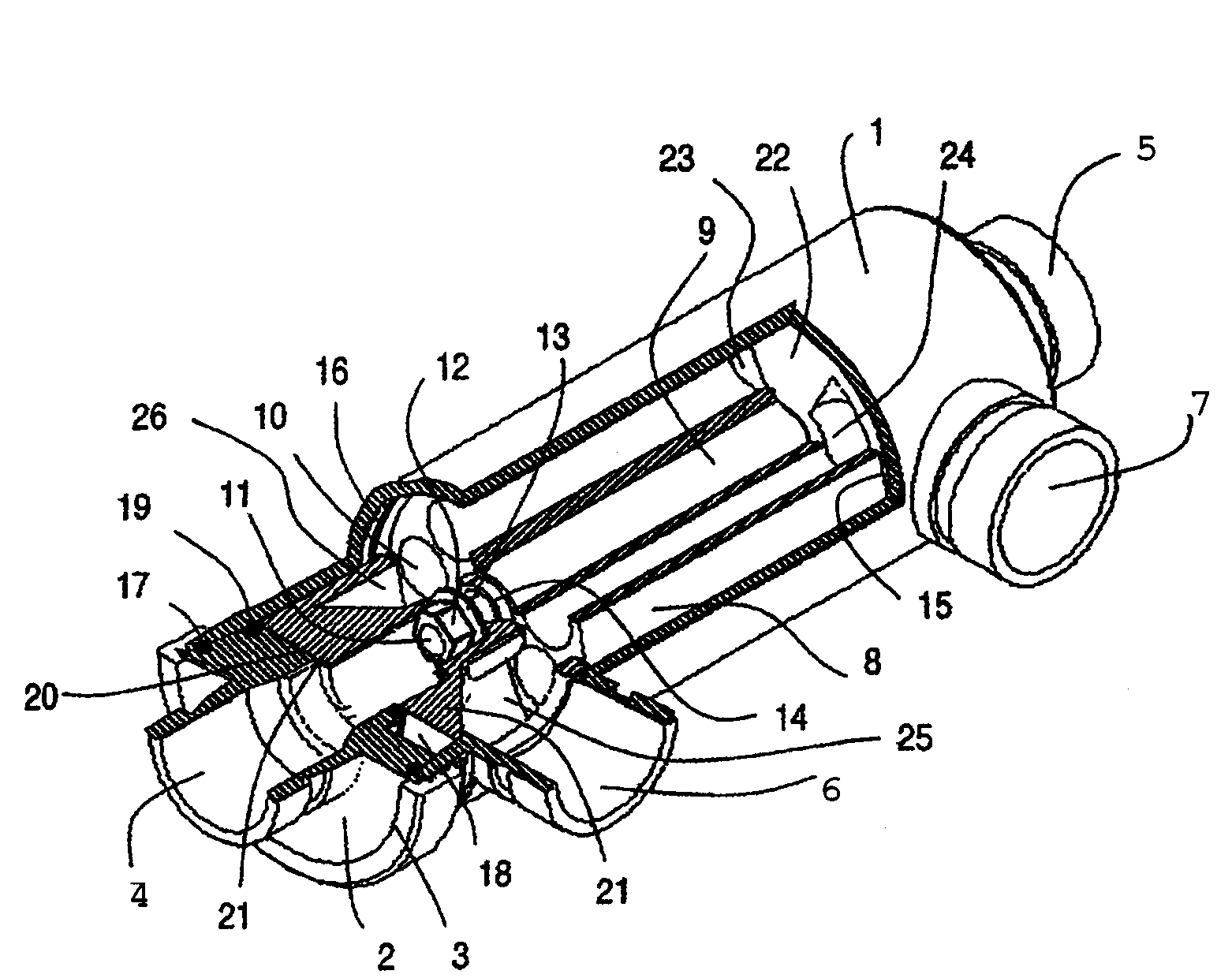
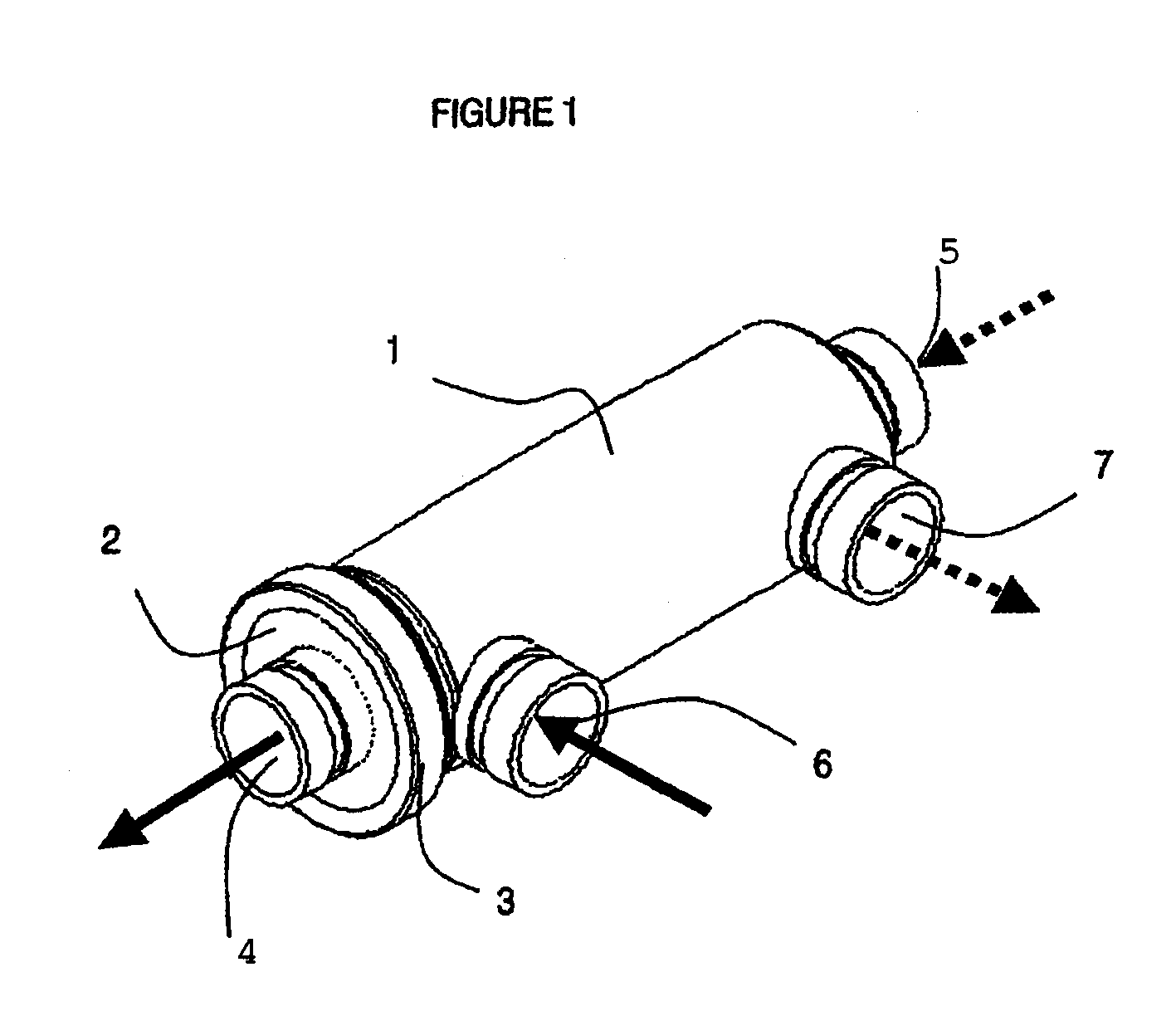
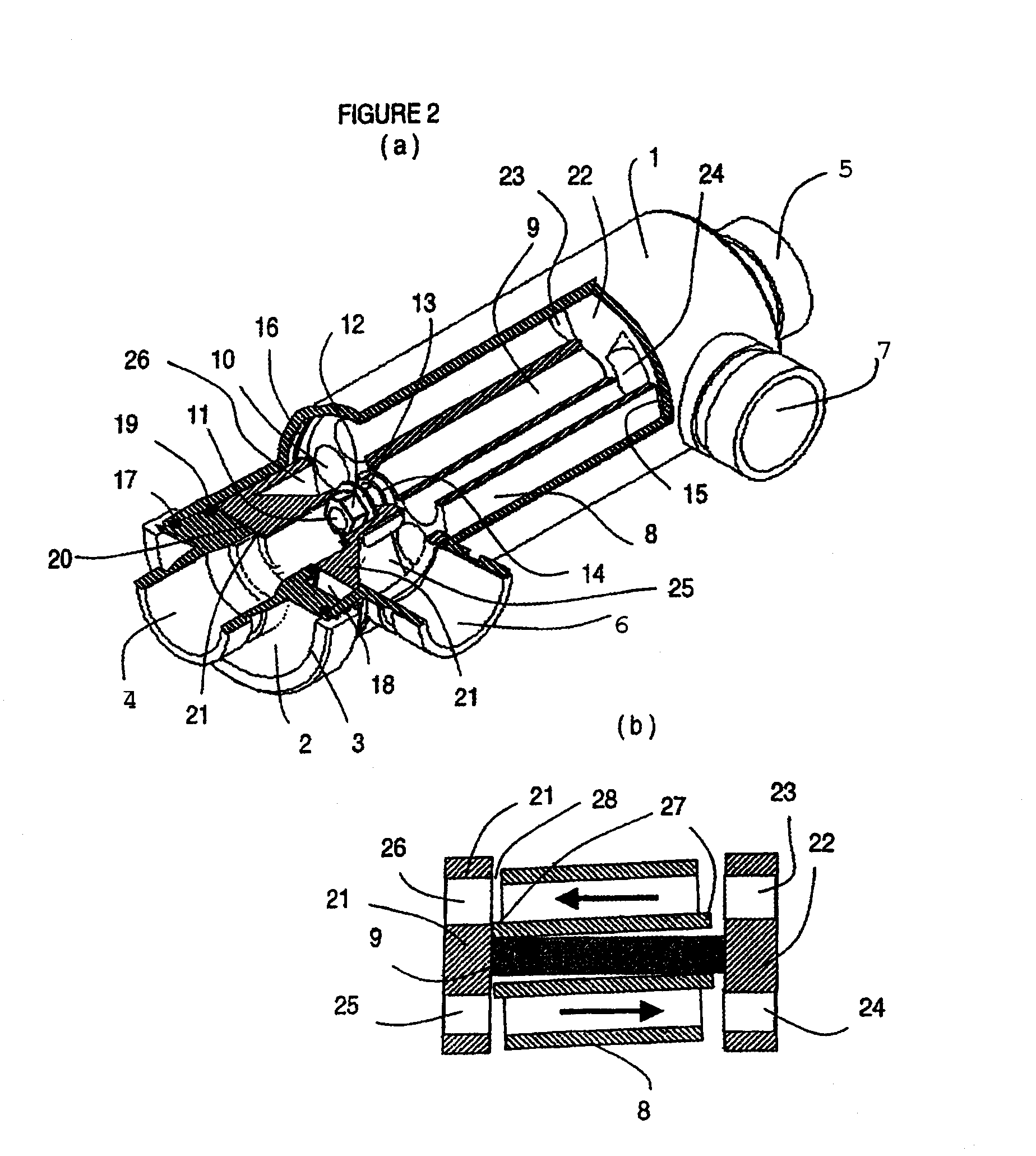
[0025]Referring now to FIG. 1, an external embodiment of a pressure exchanger according to at least one embodiment of the invention is illustrated. The pressure exchanger depicted in FIG. 1 comprises a pressure vessel 1 with a removable end cap or end cover 2 having a low-pressure fluid outlet 4 a...


PUM


Abstract

A pressure exchanger for transferring pressure energy from a high-pressure fluid stream to low-pressure fluid stream. A ducted rotor is positioned on a central axle between two end covers inside the vessel with a coaxial inlet and outlet pair that is in communication with a pair of low pressure ports having inclination forming an inlet tangential velocity vector in the direction of rotor rotation and an outlet tangential velocity vector in opposite direction imparting a rotational momentum on rotor. A pair of high-pressure ports is adapted for flow without inclination and imparts no momentum to the rotor. The end covers have a sloped surface following a flat sealing area that increases the clearance in the direction of rotation causing increased outflow during depressurization and lower duct pressure. This also causes increased inflow during the pressurization phase which will dissipate pressure energy as opposed to producing cavitation or pressure waves.

Description

CROSS REFERENCE TO RELATED APPLICATIONS[0001]This application claims priority to provisional application No. 60 / 599,760, entitled “Pressure Exchanger” filed Aug. 10, 2004, the disclosure of which is hereby incorporated by reference in its entirety.FIELD OF THE INVENTION[0002]The invention relates to a pressure exchanger for transfer of pressure energy from one fluid flow to another, contained inside a pressure vessel with inlet and outlets for each fluid flow in communication through a rotor with multiple through-going coaxial ducts and arranged for rotation through its longitudinal axis between opposing end covers guiding fluid exchange of a first and second fluid stream within and external of the rotor.BACKGROUND AND DESCRIPTION OF THE RELATED ART[0003]Commercial pressure exchangers of the above-mentioned category are known to exhibit operational flow limitations due to excessive noise, flow resistance, intermixing and cavitation despite the application of above mentioned patents....

Claims


Application Information

Patent Timeline
Patent Type & Authority Patents(United States)
IPC IPC(8): F04F11/00B01D61/00F02C3/02F04F99/00
CPCF04F13/00B01D61/06Y02A20/131
Inventor HAUGE, LEIF
Owner ISOBARIC STRATEGIES INC
Why Eureka
Try Eureka