Oscillating air jets for implementing blade variable twist, enhancing engine and blade efficiency, and reducing drag, vibration, download and ir signature

a technology of variable twisting and oscillating air jets, applied in the direction of rotors, vessel parts, vessel construction, etc., can solve the problems of increasing mechanical complexity of aircraft, limited in the ability to respond quickly and efficiently, and inconvenient us

Inactive Publication Date: 2003-04-08
MCDONNELL DOUGLAS
View PDF51 Cites 67 Cited by
  • Summary
  • Abstract
  • Description
  • Claims
  • Application Information

AI Technical Summary

Problems solved by technology

The prior art continues to encounter problems with providing controllable aerodynamic surfaces on rotor blades, wings, engine inlets, helicopter fuselages, and nozzles.
Although these control surfaces can mechanically alter the geometry of the original aerodynamic device, they are limited in ability to respond quickly and efficiently.
Prior art mechanical control surfaces can add mechanical complexity to the aircraft, can compromise structural integrity, can complicate manufacturing and can compromise radar detectability.
Unfortunately, BVI noise is typically within a frequency range which is highly important to human subjective response.
Additionally, it is easily detected electronically at large distances, thus increasing the vulnerability of military rotorcraft.
The result of these measures is a decrease in the strength of the interaction between the rotor blade and the tip vortices.
Each of the prior art solutions to BVI noise has been at least partially unsuccessfu

Method used


Image

  • Oscillating air jets for implementing blade variable twist, enhancing engine and blade efficiency, and reducing drag, vibration, download and ir signature
  • Oscillating air jets for implementing blade variable twist, enhancing engine and blade efficiency, and reducing drag, vibration, download and ir signature
  • Oscillating air jets for implementing blade variable twist, enhancing engine and blade efficiency, and reducing drag, vibration, download and ir signature

Examples


Embodiment Construction

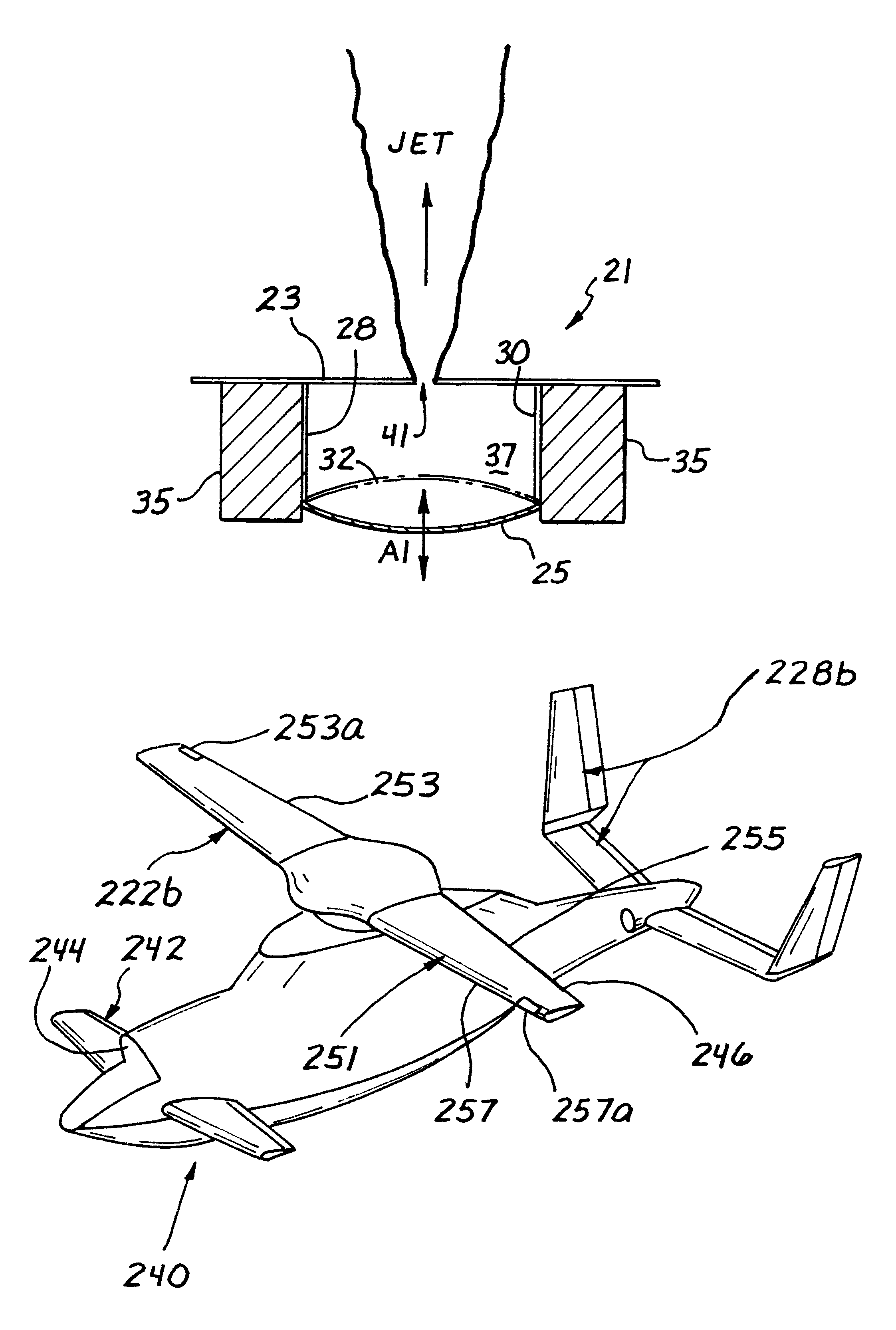
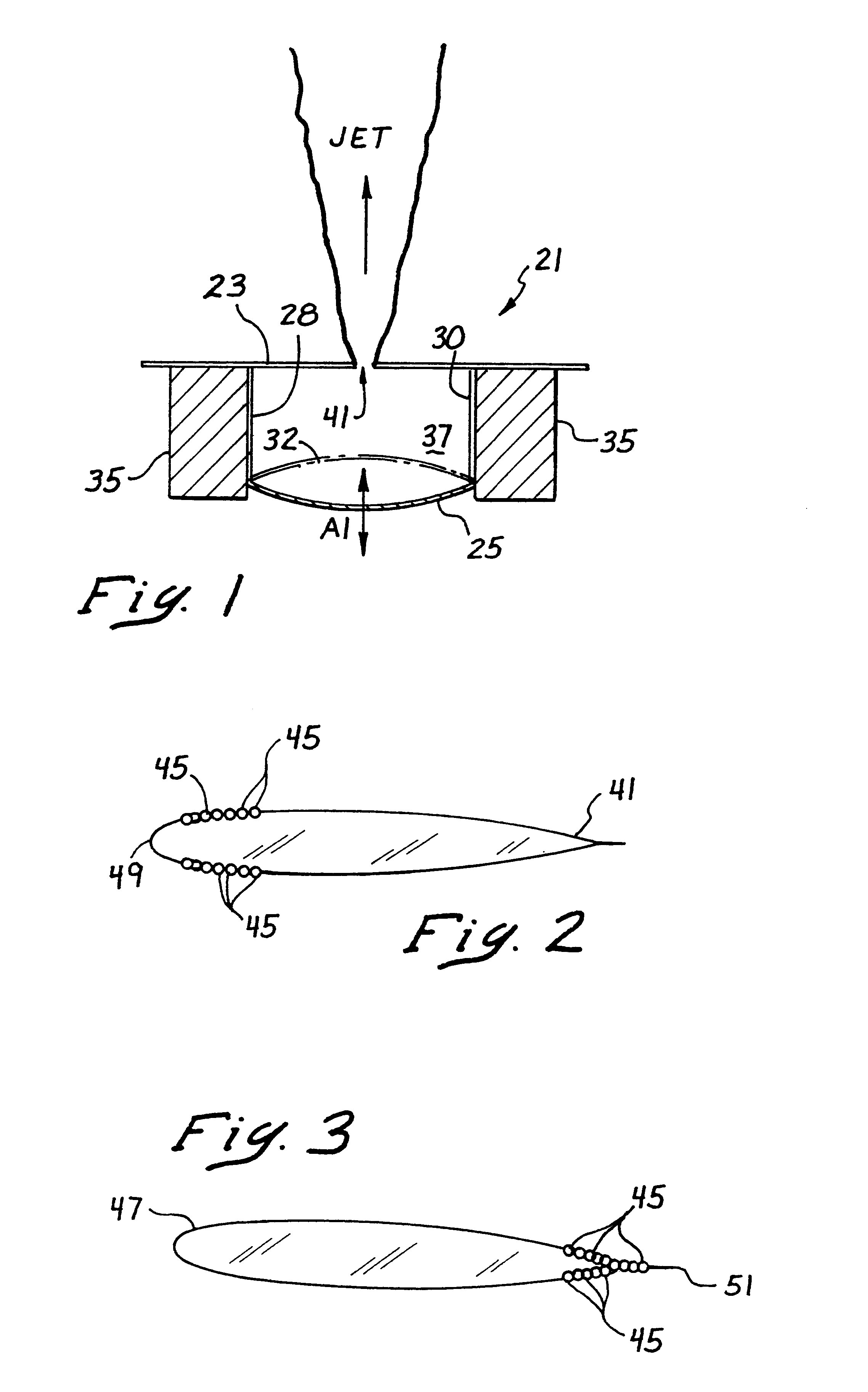
Referring now more particularly to the drawings, FIG. 1 illustrates an oscillating air jet assembly 21 which is disposed on an aerodynamic surface 23. The assembly 21 comprises a diaphragm 25 formed of a piezoelectric material. The diaphragm 25 is preferably supported between a first conductor 28 and a second conductor 30, and is movable in the directions of the arrows Al between a first position indicated by the reference numeral 25 and a second position indicated by the phantom lines 32.

A chassis 35 secures the first conductor 28 and the second conductor 30 to the diaphragm 24. An oscillating current is provided to the diaphragm 25 via the first conductor 28 and the second conductor 30, to thereby electrically stimulate the diaphragm 25 to oscillate in directions of the arrows Al.

Movement of the diaphragm from a first position to a position 32 shown in phantom produces a positive pressure within the sealed chamber 37, and movement of the diaphragm in the opposite direction produce...


PUM


Abstract

A porous surface on an aircraft structure driven with oscillating positive and negative pressures is used as an active control device for attenuating negative aerodynamic interactions. The porous surfaces can be driven with positive and negative pressures either continuously or when predetermined flight conditions are present. The porous surfaces can be used on rotor blades to reduce BVI noise in descent flight conditions. The porous surfaces can be configured on rotor blades for affecting blade variable twist in accordance with various flight conditions, and can further be incorporated for reducing rotor hub vibrations as well. Porous surfaces placed on aerodynamic surfaces below the rotor blades of a tiltrotor aircraft can attenuate or eliminate download and fountain flow conditions. When placed on the trailing edges of a tip jet-exhaust driven rotor blade, the porous surfaces of the present invention can supplement the tip jet momentum of the exhaust to thereby reduce an amount of exhaust needed to drive the rotor blade.

Description

1. Field of the InventionThis invention relates generally to aerodynamic surfaces and, more particularly, to improved constructions and control schemes for such aerodynamic surfaces which provide for aerodynamic control and for significant reductions in noise in the case of rotor blades.2. Description of Related ArtThe prior art continues to encounter problems with providing controllable aerodynamic surfaces on rotor blades, wings, engine inlets, helicopter fuselages, and nozzles. Movable control surfaces placed on these aerodynamic surfaces have included flaps, slots, spoilers, ailerons, elevators, and rudders. Although these control surfaces can mechanically alter the geometry of the original aerodynamic device, they are limited in ability to respond quickly and efficiently. Prior art mechanical control surfaces can add mechanical complexity to the aircraft, can compromise structural integrity, can complicate manufacturing and can compromise radar detectability.Conventional helico...

Claims


Application Information

Patent Timeline
IPC IPC(8): B64C23/00B64C27/32B64C27/00B64C23/04B64C27/467B64C27/51
CPCB64C23/04B64C27/001B64C27/467B64C27/51B64C2027/725Y02T50/166B64C2230/28B64C2230/02B64C2230/06B64C2230/04B64C2230/14B64C2230/22B64C2230/18Y02T50/34Y02T50/10Y02T50/30
Inventor HASSAN, AHMED A.STRAUB, FRIEDRICH K.DOMZALSKI, DAVID B.
Owner MCDONNELL DOUGLAS
Why Eureka
Try Eureka