Isolated resonator gyroscope

a gyroscope and resonator technology, applied in the field of gyroscopes, can solve the problems of large and heavy, large and heavy, and the mechanism of older conventional gyroscopes is very heavy, and achieves the effects of improving the accuracy of gyroscopes

Inactive Publication Date: 2003-02-13
THE BOEING CO
View PDF0 Cites 68 Cited by
  • Summary
  • Abstract
  • Description
  • Claims
  • Application Information

AI Technical Summary

Problems solved by technology

Older conventional gyroscopes were very heavy mechanisms, employing relatively large spinning masses by current standards.
However, both of these types of gyroscopes are expensive, large and heavy.
This transfer or coupling admits external disturbances and energy loss indistinguishable from inertial rate input and hence leads to sensing errors and drift.
Other planar tuning fork gyroscopes may achieve a degree of isolation of the vibration from the baseplate, however these gyroscopes lack the vibrational symmetry desirable for tuned operation.
In addition, shell mode gyroscopes, such as the hemispherical resonator gyroscope and vibrating ring gyroscope, which can have desirable isolation and vibrational symmetry attributes, are not suitable for thin planar silicon implementation with sensitive electrostatic sensors and actuators that take advantage of the large planar areas of the device
The scale of previous silicon microgyroscopes (e.g., U.S. Pat. No. 5,894,090) has not been optimized for navigation grade performance resulting in higher noise and drift than desired.
This problem stems from use of thin eptiaxially grown silicon flexures to define critical vibration frequencies that are limited to 0.1% thickness accuracy and limit device sizes to a few millimeters.
The former results in high drift due to vibrational asymmetry or unbalance and the latter results in high rate noise due to lower mass i

Method used


Image

  • Isolated resonator gyroscope
  • Isolated resonator gyroscope
  • Isolated resonator gyroscope

Examples


Embodiment Construction

[0019] In the following description, reference is made to the accompanying drawings which form a part hereof, and which is shown, by way of illustration, several embodiments of the present invention. It is understood that other embodiments may be utilized and structural changes may be made without departing from the scope of the present invention.

[0020] 1.0 Overview

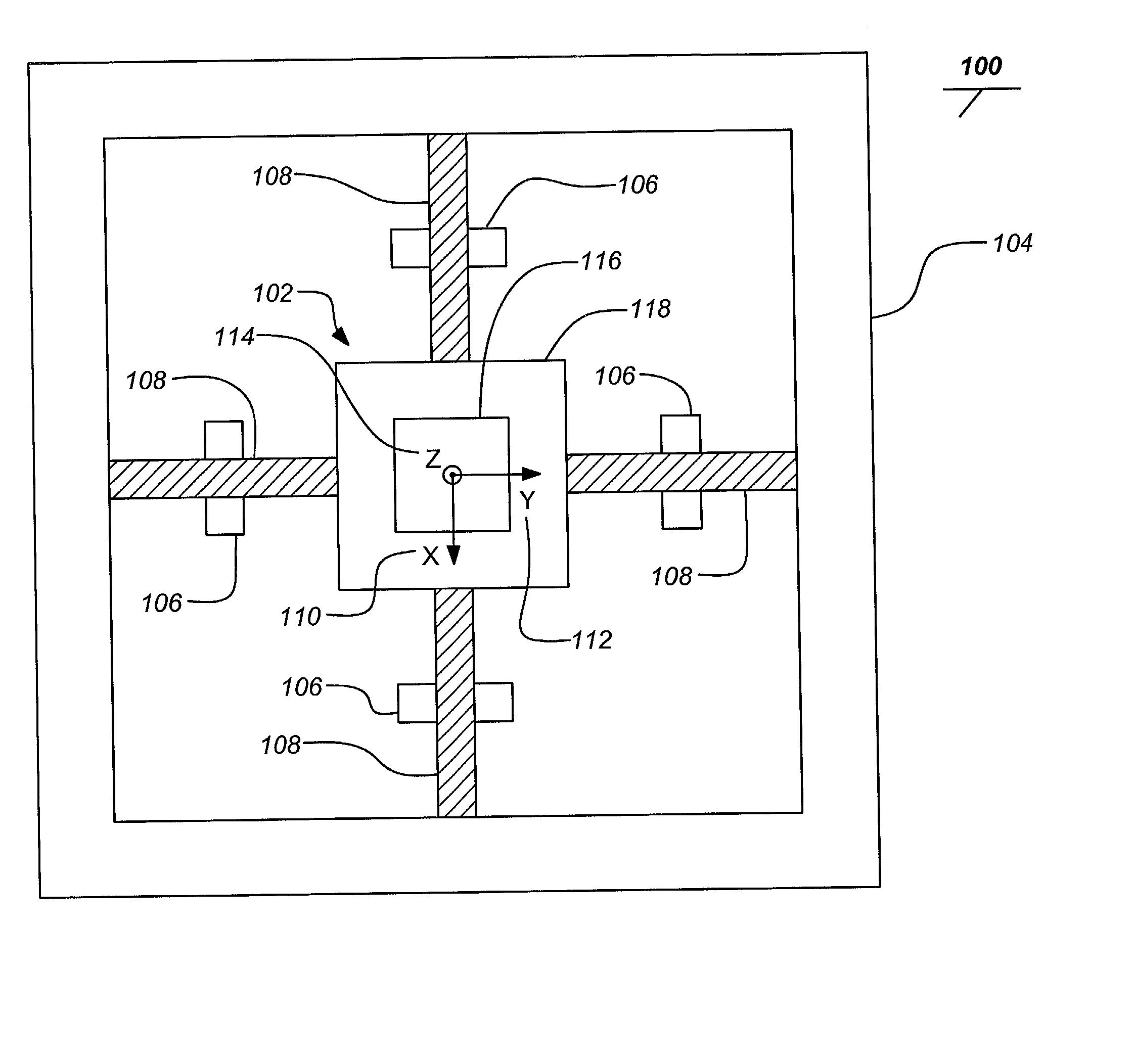
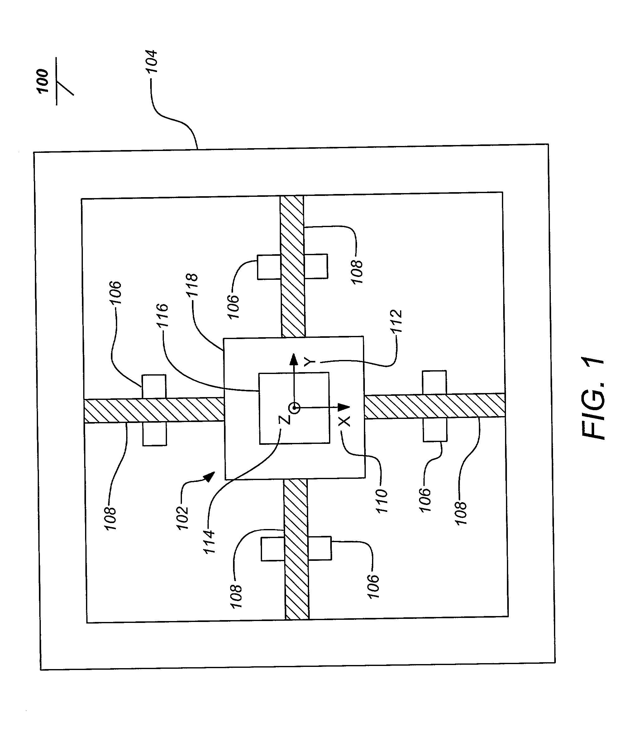
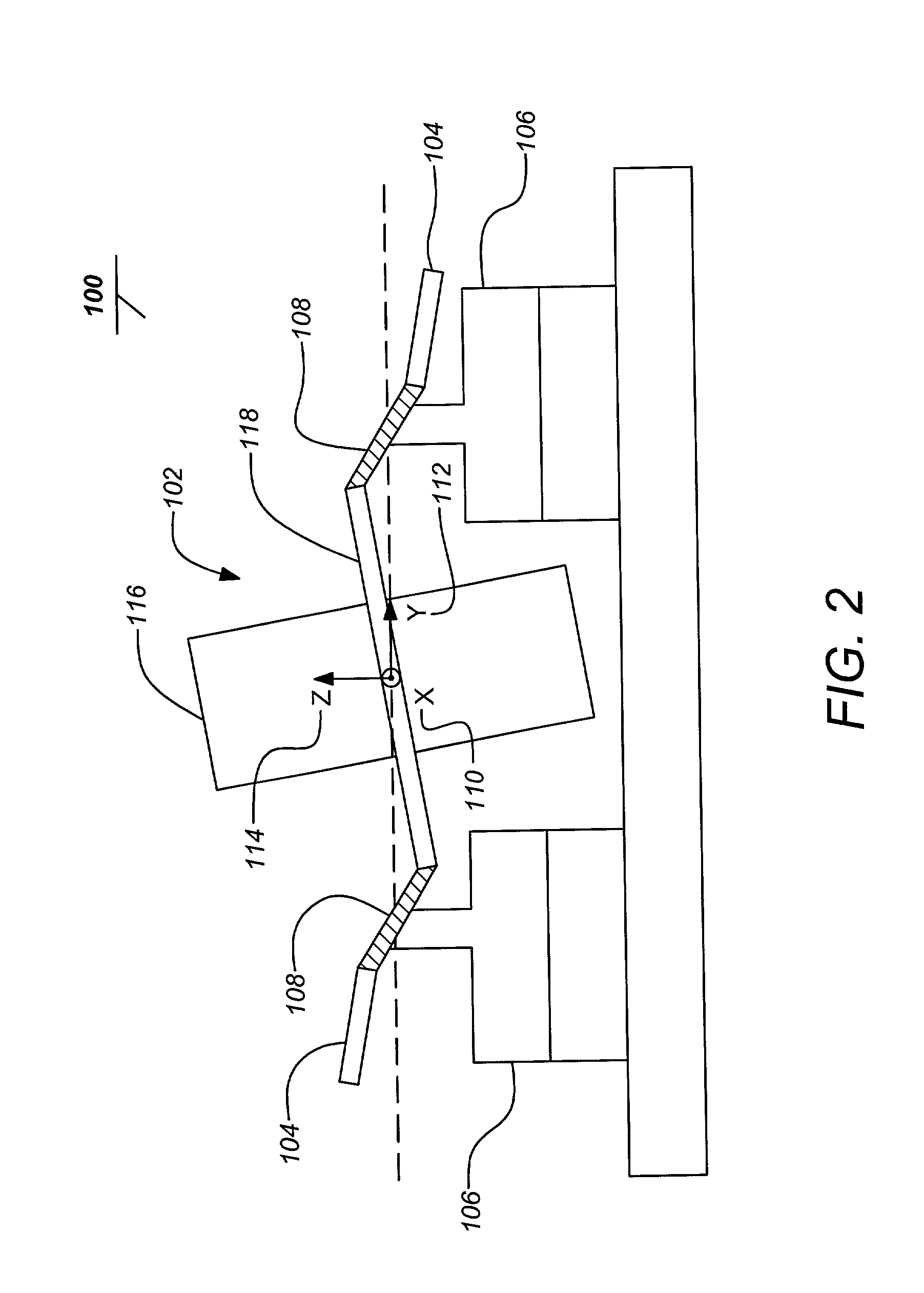
[0021] The key principle of the present invention is to provide a resonator comprising two bodies with transverse intertia symmetry about an axis aligned with an input axis and elastically supported so that their axes of symmetry and centers of mass coincide and together form two differential rocking modes of vibration transverse to the axis of symmetry. The two bodies are supported in a case having an inertial rate input axis and exhibit substantially equal frequencies distinct from other modes of vibration, mutually orthogonal and imparting substantially zero net momentum to the case. There is further an internal actuat...


PUM

PropertyMeasurementUnit
Massaaaaaaaaaa
Flexibilityaaaaaaaaaa
Inertiaaaaaaaaaaa

Abstract

The present invention discloses a resonator gyroscope comprising a resonator including two bodies, each with a center of mass and transverse inertia symmetry about an axis that are substantially coincident and each supported by one or more elastic elements and wherein the bodies together forming two differential rocking modes of vibration transverse to the axis with substantially equal frequencies and wherein the two bodies transfer substantially no net momentum to the baseplate when the resonator is excited. The gyroscope further includes a baseplate affixed to the resonator by the one or more elastic elements and sense and drive elements each affixed to the resonator and baseplate.

Description

[0002] 1. Field of the Invention[0003] The present invention relates to gyroscopes, and in particular to improved resonator microgyroscopes and their manufacture.[0004] 2. Description of the Related Art[0005] Gyroscopes are used to determine direction based upon the sensed inertial reaction of a moving mass. In various forms they are often employed as a critical sensor for vehicles such as aircraft and spacecraft. They are generally useful for navigation or whenever it is necessary to determine the orientation of a free object.[0006] Older conventional gyroscopes were very heavy mechanisms, employing relatively large spinning masses by current standards. A number of recent technologies have brought new forms of gyroscopes, including optical gyroscopes such as laser gyroscopes and fiberoptic gyroscopes as well as vibratory gyroscopes.[0007] Spacecraft often depend on inertial rate sensing gyroscopic systems to supplement attitude control. Typical systems employ conventional spinning ...

Claims


Application Information

Patent Timeline
IPC IPC(8): B81B3/00G01C19/5719
CPCG01C19/5719Y10T29/49007Y10T74/12G01P2015/084
Inventor CHALLONER, A. DORIAN
Owner THE BOEING CO
Why Eureka
Try Eureka