Airbag apparatus for vehicles

a technology for airbags and vehicles, applied in the direction of vehicular safety arrangements, vehicle components, pedestrian/occupant safety arrangements, etc., can solve the problems of reduce the number of parts and manufacturing costs, and minimize the loss of airbag cushion pressure

Active Publication Date: 2011-09-06
HYUNDAI MOTOR CO LTD +1
View PDF23 Cites 2 Cited by
  • Summary
  • Abstract
  • Description
  • Claims
  • Application Information

AI Technical Summary

Benefits of technology

[0011]Various aspects of the present invention are directed to provide an airbag apparatus for vehicles, which allows the deploying direction of an airbag cushion to correspond to the hinge expanding direction of an airbag deployment door, thus mining the loss of pressure of the airbag cushion.
[0019]In various aspects, the present invention allows the deploying direction of an airbag cushion to correspond to the hinge expanding direction of an airbag deployment door, thus realizing the rapid expansion of a hinge and minimizing the loss of airbag cushion pressure.
[0020]Furthermore a door reinforcing plate supporting the airbag deployment door of a crash pad cover may be integrated with a chute, thus reducing the number of parts and manufacturing cost.

Problems solved by technology

The conventional airbag apparatus is problematic in that when a crash occurs, the deploying direction of the airbag cushion 21 is not identical with the hinge expanding direction of the hinge plate 15, as shown in FIGS. 7A to 7D, so that the expansion of the hinge is retarded, and the pressure of the airbag cushion is lost due to the for the expansion of the hinge.

Method used


Image

  • Airbag apparatus for vehicles
  • Airbag apparatus for vehicles
  • Airbag apparatus for vehicles

Examples


Embodiment Construction

[0030]Reference will now be made in detail to various embodiments of the present invention(s), examples of which are illustrated in the accompanying drawings and described below. While the invention(s) will be described in conjunction with exemplary embodiments, it will be understood that present description is not intended to limit the invention(s) to those exemplary embodiments. On the contrary, the invention(s) is / are intended to cover not only the exemplary embodiments, but also various alternatives, modifications, equivalents and other embodiments, which may be included within the spirit and scope of the invention as defined by the appended claims.

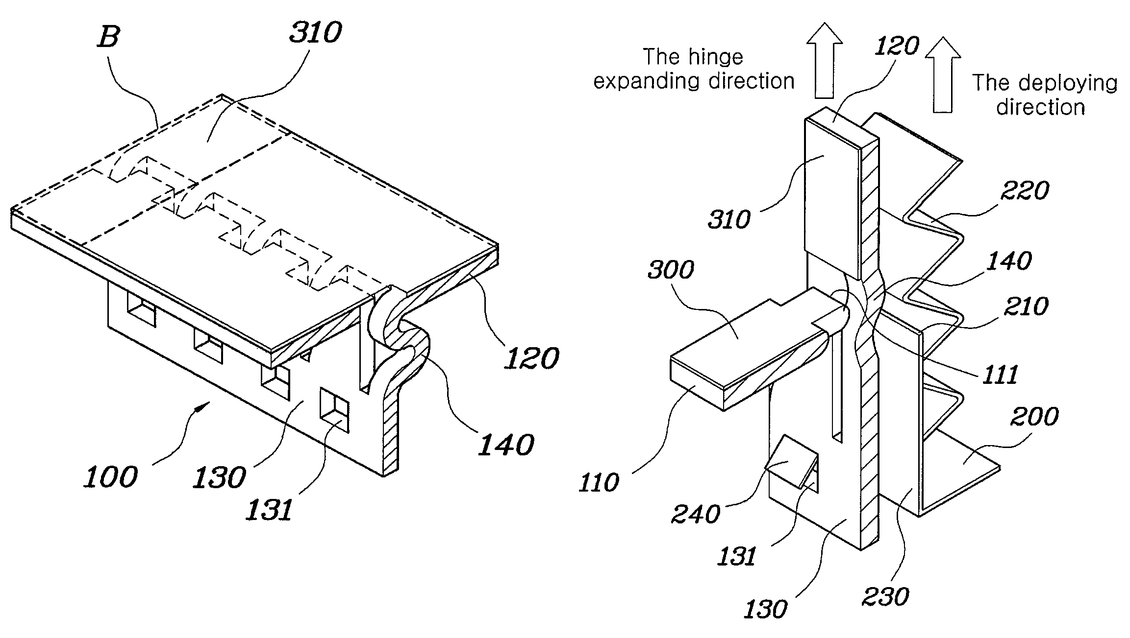
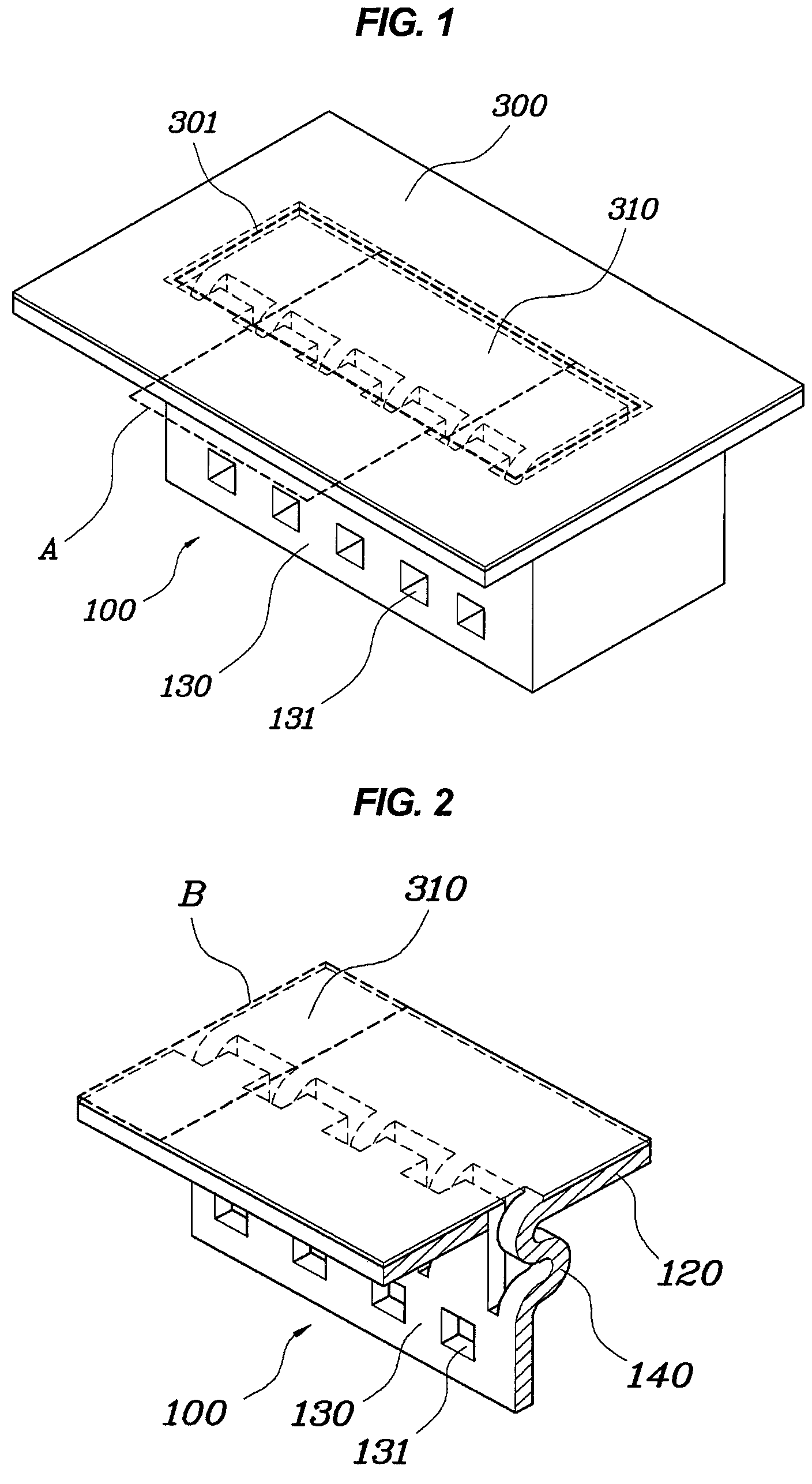
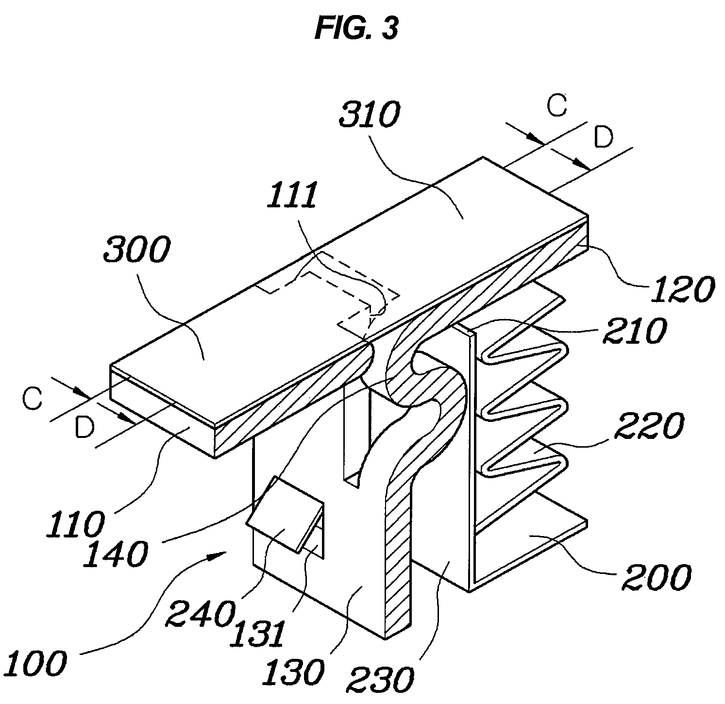
[0031]As shown in FIGS. 1 to 4B, the airbag apparatus according to various embodiments of the present invention allows the hinge expanding direction of an airbag deployment door 310 relative to a crash pad cover 300 to correspond to the deploying direction of the airbag cushion when the airbag is deployed, thus realizing the rapid exp...


PUM


Abstract

Disclosed herein is an airbag apparatus for vehicles, which is capable of minimizing the loss of pressure of an airbag cushion. The airbag housing of the airbag apparatus accommodates an airbag cushion which is deployed through an opening. An airbag deployment door is placed to face the opening and separated from the cut notch of a crash pad cover when the airbag cushion is deployed. A chute is connected to a surface of the airbag deployment door through a curved hinge portion which is placed to be parallel to the sidewall of the airbag housing.

Description

CROSS-REFERENCE TO RELATED APPLICATIONS[0001]The present application claims priority to Korean Patent Application Number 10-2008-0120702 filed Dec. 1, 2008, the entire contents of which application is incorporated herein for all purpose by this reference.BACKGROUND OF THE INVENTION[0002]1. Field of the Invention[0003]The present invention relates to an airbag apparatus for vehicles, which is capable of minimizing the loss of pressure of an airbag cushion.[0004]2. Description of Related Art[0005]Generally, an airbag apparatus for vehicles includes an airbag cushion, a housing for accommodating the airbag cushion therein and an inflator for inflating the airbag cushion.[0006]As shown in FIG. 6, in a conventional airbag apparatus for vehicles, a door 12 is provided on an instrument panel 10 to enable the deployment of an airbag through a cut line 11. Further, a chute 14 is coupled to the instrument panel 10 through fusion, and a reaction plate 13 is coupled to the door 12 through fusio...

Claims


Application Information

Patent Timeline
Patent Type & Authority Patents(United States)
IPC IPC(8): B60R21/205B60R21/215
CPCB60R21/215B60R2021/21537B60R21/2155B60R21/205B60R21/2165B60R21/045B60R2021/024
Inventor KONG, BYUNG SEOK
Owner HYUNDAI MOTOR CO LTD
Why Eureka
Try Eureka