Valve Apparatus

a valve and valve body technology, applied in mechanical devices, generators/motors, transportation and packaging, etc., can solve the problems of disturbances during fluid switching, inefficient fluid cycling, and reduced fluid pulse quality, etc., to achieve smooth and energetically efficient, simple structure and operation, and reasonable cost

Inactive Publication Date: 2011-04-28
ABB RES LTD
View PDF16 Cites 6 Cited by
  • Summary
  • Abstract
  • Description
  • Claims
  • Application Information

AI Technical Summary

Benefits of technology

[0011]It is a particular object of the invention to provide such valve apparatus, which can provide for a smooth and energetically efficient cycling of fluid while the phase shifts between fluid pulses from different outlets or from laterally separated portions of a fluid pulse can be controll

Problems solved by technology

A problem of such arrangement is that energetically inefficient cycling of fluid is achieved and that disturbances during fluid switching occur.
However, the larger the total area of the outlets is, the larger is the tendency for the fluid pulses to mix during switching, which reduces the quality of the train of fluid pulses, unless the nu

Method used


Image

  • Valve Apparatus
  • Valve Apparatus
  • Valve Apparatus

Examples


Embodiment Construction

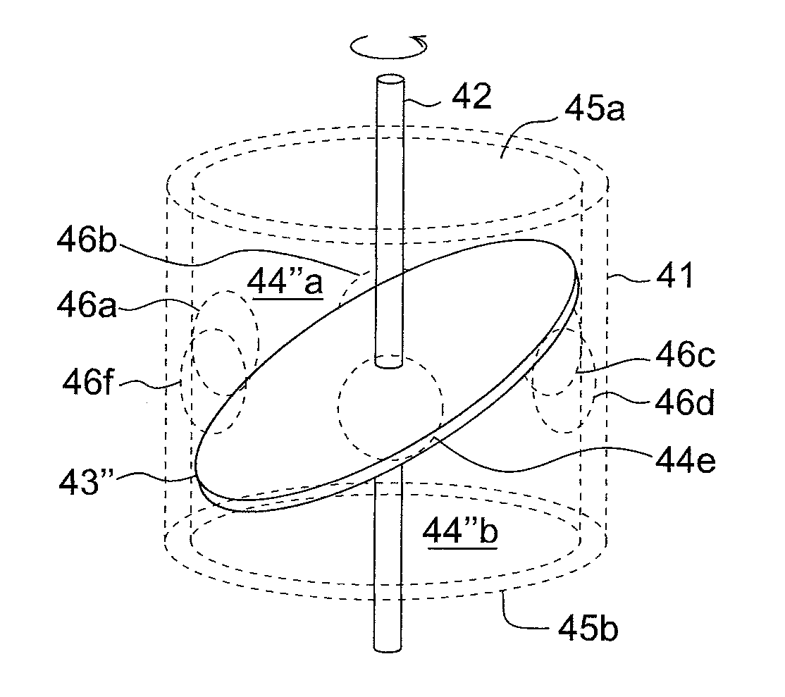
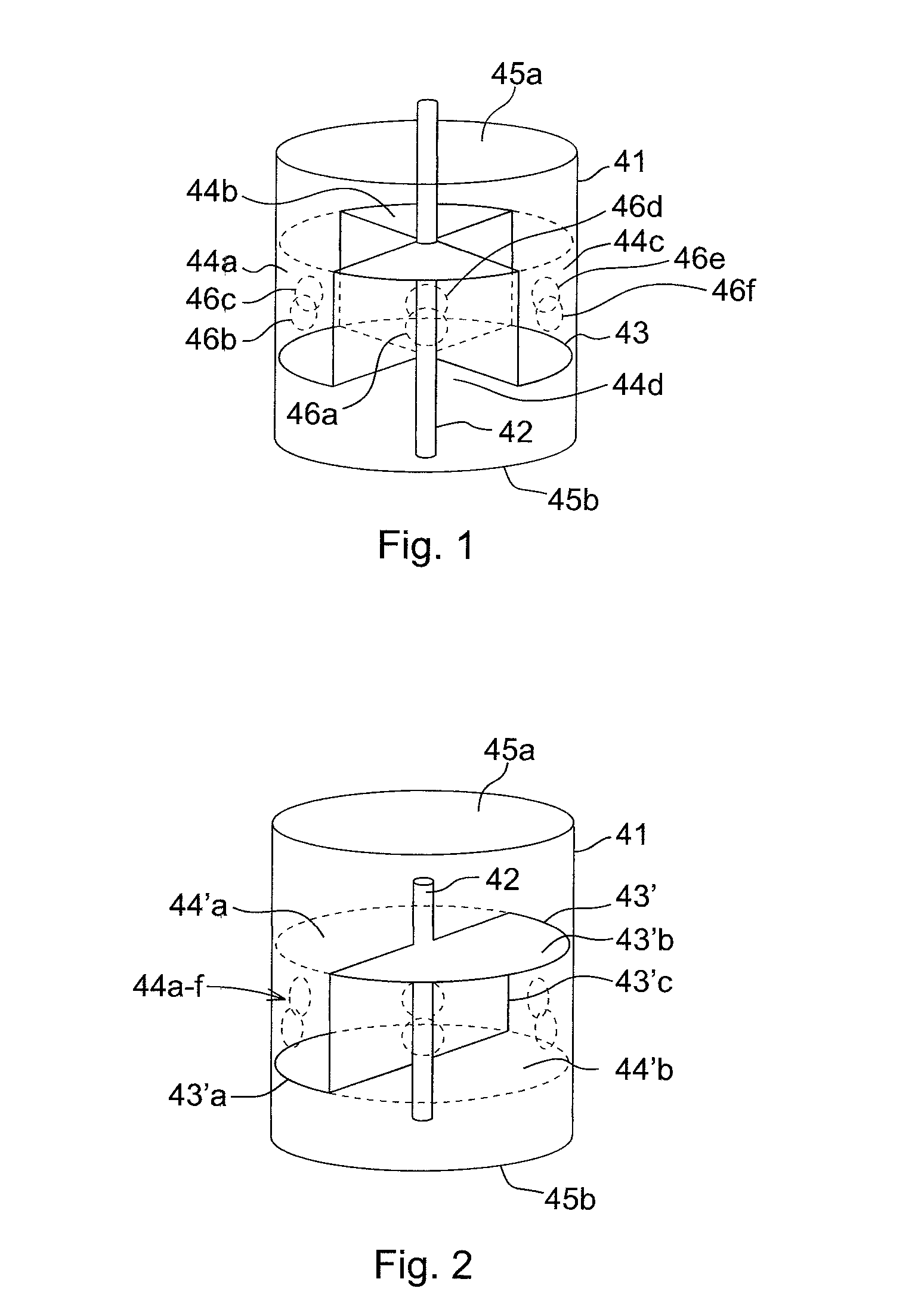
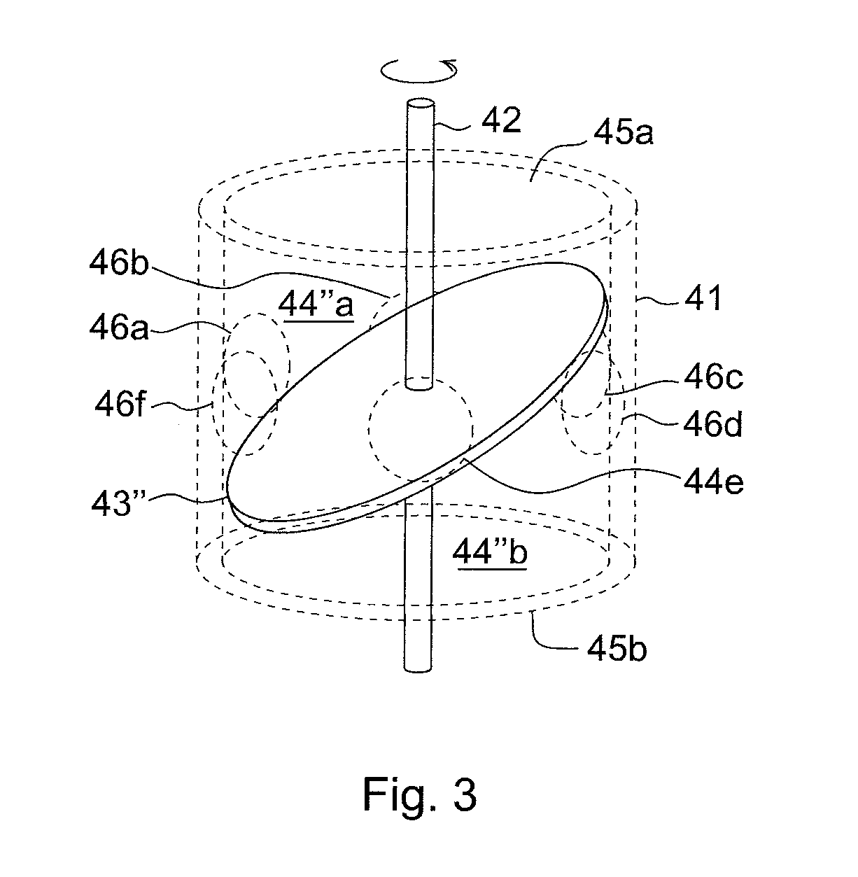
[0025]A rotating valve apparatus is disclosed in FIG. 1. A hollow cylinder or cylindrical casing 41 houses a symmetrically arranged rotatable shaft 42, to which a member 43 is fixedly attached. The member 43, which preferably is thermally isolating, is provided in close fit with the cylindrical casing 41 and defines four essentially separated and identical compartments or chambers 44a-d of the apparatus. Each of the chambers 44a-d is defined by two sidewalls that extends radially from the shaft 42 and to the casing 1 and axially, and a top cover that extends radially from the shaft 42 and to the casing 1 and circumferentially between the two sidewalls. Two of the chambers 44a, 44c are constantly in fluid communication with a first axially arranged inlet 45a, and is configured to receive or output fluid of a first characteristic, and two of the chambers 44b, 44d are constantly in fluid communication with a second axially arranged inlet 45b, and is configured to receive or output flui...


PUM


Abstract

A rotating valve apparatus includes a cylindrical casing; a shaft arranged symmetrically in the casing; a member fixedly attached to the shaft and in close fit with the cylindrical casing, defining separated chambers within the casing; at least one outlet fixedly arranged along the circumference of the casing; and a plurality of axially arranged inlets, each of which being constantly in fluid communication with a respective one of the separated chambers, wherein the axially arranged inlets are alternately in fluid connection with the outlet fixedly arranged along the circumference of the casing in response to rotation of the shaft and the member with respect to the casing. The outlet(s) has/have a fluid path length that varies along the circumference of the casing depending on the rotational speed of the shaft such that the interfaces between fluids originating from different ones of the axially arranged inlets will be essentially vertical to the flow direction of the fluids.

Description

CROSS-REFERENCE TO RELATED APPLICATIONS[0001]The present application is a continuation of pending International patent application PCT / EP2009 / 054866 filed on Apr. 23, 2009, which designates the United States and claims priority from European patent application 08155478.4 filed on Apr. 30, 2008, the content of which is incorporated herein by reference.FIELD OF THE INVENTION[0002]The present invention generally relates to valve apparatuses. The invention is preferably, but not exclusively, intended for a generator system for converting thermal energy to electric energy.BACKGROUND OF THE INVENTION[0003]In known generator systems for converting thermal energy to electric energy there is provided a magnetic circuit of a suitable magnetic material and a coil arranged around the magnetic circuit. A temperature-varying arrangement varies the temperature of the magnetic circuit alternately above and below a phase transition temperature such as the Curie point to thereby vary the reluctance o...

Claims


Application Information

Patent Timeline
IPC IPC(8): H01L37/04F16K5/00
CPCF16K11/076Y10T137/86863Y10T137/86871
Inventor RUSSBERG, GUNNAR
Owner ABB RES LTD
Why Eureka
Try Eureka