Method of manufacturing heat exchanger and heat exchanger

a manufacturing method and heat exchanger technology, applied in indirect heat exchangers, lighting and heating devices, membranes, etc., can solve the problems of increasing reducing the efficiency of the heat exchanger, and reducing the overall length of the hollow fiber membrane for one round trip. , the effect of reducing the pressure loss of the heat medium passing through the hollow portion

Active Publication Date: 2016-11-17
TERUMO KK
View PDF1 Cites 6 Cited by
  • Summary
  • Abstract
  • Description
  • Claims
  • Application Information

AI Technical Summary

Benefits of technology

[0014]According to the present invention, the overall length of each of the hollow fiber membranes for one round trip can be shortened as much as possible. Accordingly, in the hollow fiber membrane layer, a pressure loss of the heat medium passing through the hollow portion of each of the hollow fiber membranes is reduced. Accordingly, the hollow fiber membrane layer becomes excellent in the heat exchanger effectiveness.
[0015]In addition, the diameter of the hollow fiber membrane can be decreased in size as much as possible by the quantity of the reduced pressure loss of the heat medium, that is, it is possible to realize reduction of the hollow fiber membrane in size. Accordingly, the volume of the hollow fiber membrane layer can be decreased. Therefore, it is possible to reduce a filling amount of a fluid which becomes a target subjected to heat exchange.

Problems solved by technology

In the heat exchanger including the hollow fiber membrane layer having such a configuration, when the heat medium passes through the inside of the hollow fiber membrane, the passing distance thereof for obtaining sufficient heat exchange is not ensured.
However, as the number of times of winding the hollow fiber membrane increases, the overall length of the hollow fiber membrane becomes elongated.
In proportion thereto, there is a problem of an increase of a pressure loss of the heat medium passing through the inside of the hollow fiber membrane.
Accordingly, there is a concern that the heat exchanger effectiveness deteriorates.
However, as the number of times of winding each of the hollow fiber membranes increases, the total volume of the gaps among and between the hollow fiber membrane increases.
As a result thereof, the quantity of blood passing through the gaps, that is, a blood filling amount (i.e., blood volume contained within the oxygenator) also increases, and thus, the burden to a patient becomes significant.

Method used


Image

  • Method of manufacturing heat exchanger and heat exchanger
  • Method of manufacturing heat exchanger and heat exchanger
  • Method of manufacturing heat exchanger and heat exchanger

Examples


first embodiment

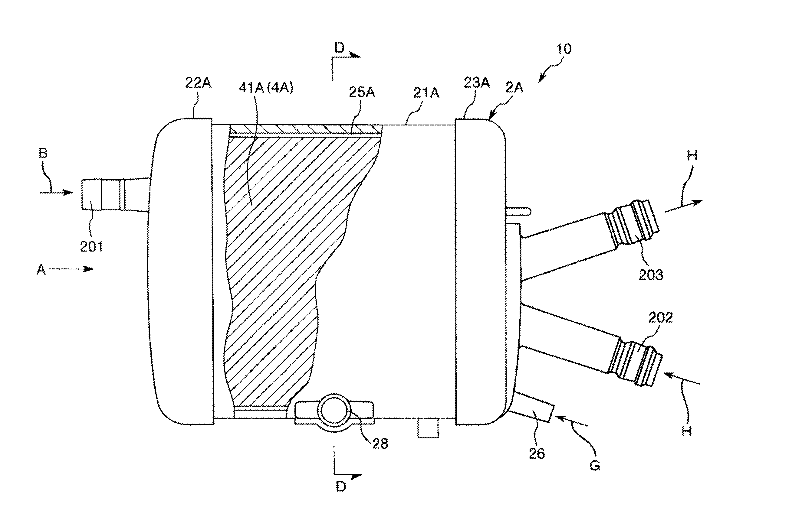
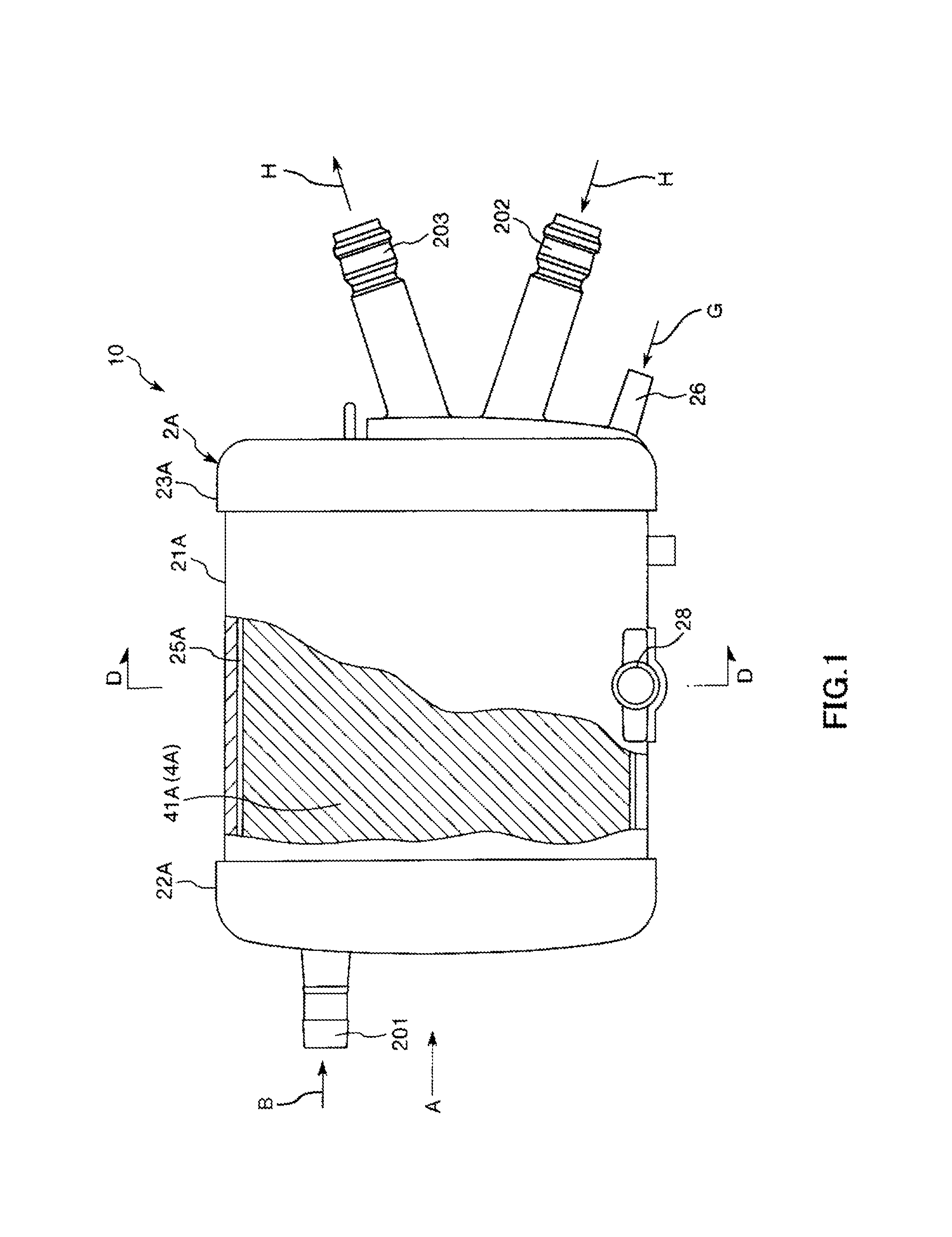
[0033]Note that, in FIGS. 1, 3, 4, and 7 to 10 (similar in FIGS. 11 and 16), the left side will be referred to as “left” or “left-hand side (one side)”, and the right side will be referred to as “right” or “right-hand side (the other side)”. In addition, in FIGS. 1 to 6 (similar in FIGS. 11 and 16), the inner side of the oxygenator will be described as “blood inlet side” or “upstream side”, and the outer side thereof will be described as “blood outlet side” or “downstream side”.

[0034]An oxygenator 10 illustrated in FIGS. 1 to 5 has an overall shape which is substantially columnar. The oxygenator 10 is equipped with a heat exchanger including a heat exchange section 10B which is provided on the inner side thereof and performs heat exchange with respect to blood, and an oxygenator section 10A as a gas exchange section which is provided on an outer circumferential side of the heat exchange section 10B and performs gas exchange with respect to blood. For example, the oxygenator 10 is us...

second embodiment

[0102]FIG. 12 is a view illustrating a fixed state of the hollow fiber membrane in the base material obtained through the method of manufacturing a heat exchanger of the present invention (second embodiment).

[0103]Hereinafter, with reference to the drawing, the second embodiment of the method of manufacturing a heat exchanger and the heat exchanger according to the present invention will be described. The points different from those in the above-described embodiment will be mainly described, and description of similar contents will be omitted.

[0104]The present embodiment is similar to the first embodiment except that the fixing method with respect to the hollow fiber membrane is different.

[0105]As illustrated in FIG. 12, in the present embodiment, a flexible fixing belt (belt-like body) 11A is used for fixing the turning-back point 312 of the hollow fiber membrane 31. The fixing belt 11A has a width wider than that of the fixing string 11. Due to the fixing belt 11A, when the portio...

third embodiment

[0107]FIG. 13 is a view illustrating a fixed state of the hollow fiber membrane in the base material obtained through the method of manufacturing a heat exchanger of the present invention in a third embodiment.

[0108]Hereinafter, with reference to the drawing, the third embodiment of the method of manufacturing a heat exchanger and the heat exchanger according to the present invention will be described. The points different from those in the above-described embodiments will be mainly described, and description of similar contents will be omitted.

[0109]The present embodiment is similar to the first embodiment except that the fixing method with respect to the hollow fiber membrane is different.

[0110]As illustrated in FIG. 13, in the present embodiment, the portion in the vicinity of the turning-back point 312 of the hollow fiber membrane 31 is fixed as follows.

[0111]First, a dryer 12 is prepared. An exhaust port 121 of the dryer 12 is oriented toward the portion in the vicinity of the ...


PUM

PropertyMeasurementUnit
outer diameteraaaaaaaaaa
flexibleaaaaaaaaaa

Abstract

A heat exchanger has a hollow fiber membrane layer comprised of a plurality of hollow fiber membrane conduits each of which has a hollow portion allowing a heat medium to pass therethrough. The conduits are derived by winding a base cord of the hollow fiber membrane onto a cylindrical body. The winding follows a generally helical trajectory around the longitudinal axis of the cylindrical body with a plurality of continuous round trips from the first end to the second end and turning back at each respective end, wherein each round trip completes a number of circumferential revolutions N, wherein N is greater than or equal to one, and wherein N is less than two.

Description

CROSS REFERENCE TO RELATED APPLICATIONS[0001]This application is a continuation of PCT Application No. PCT / JP2015 / 050244, filed Jan. 7, 2015, based on and claiming priority to Japanese application no. 2014-018076, filed Jan. 31, 2014, both of which are incorporated herein by reference in their entirety.TECHNICAL FIELD[0002]The present invention relates to a method of manufacturing a heat exchanger and a heat exchanger apparatus.BACKGROUND ART[0003]In the related art, there is a known heat exchanger having a hollow fiber membrane layer which is configured to include a plurality of hollow fiber membranes so as to form an overall shape of a cylindrical body. A hollow fiber sheet disclosed in PTL 1 can be applied to the hollow fiber membrane layer forming the cylindrical body shape. In the hollow fiber sheet disclosed in Japanese Registered Utility Model No. 2579299, the plurality of hollow fiber membranes are disposed in substantially parallel to each other so as to be the woof, and th...

Claims


Application Information

Patent Timeline
Patent Type & Authority Applications(United States)
IPC IPC(8): A61M1/16F28D21/00
CPCA61M1/1698A61M1/1629F28D2021/005A61M2207/00F28D21/0015B01D63/02B01D2313/22B01D2313/90B29L2031/753B29L2031/18B29C53/665B29C53/8083A61M1/3623
Inventor SAITO, TAKASHI
Owner TERUMO KK
Why Eureka
Try Eureka