Steam valve assembly and steam turbine plant

a technology of steam valves and steam turbines, which is applied in the direction of fluid pressure control, instruments, process and machine control, etc., can solve the problems of high labor intensity, inability to determine the center gravity of the valve body and the valve stem, and the body at the distal end of the valve stem cannot fully contact the valve seat, etc., to achieve the effect of reducing pressure loss, high efficiency and reducing the pressure loss when the valve is in an open position

Active Publication Date: 2011-10-25
KK TOSHIBA
View PDF14 Cites 6 Cited by
  • Summary
  • Abstract
  • Description
  • Claims
  • Application Information

AI Technical Summary

Benefits of technology

[0011]The present invention has been made in view of the disadvantages of the prior art described above. An object of the invention is to provide a steam valve assembly which can be maintained at high efficiency and in which the pressure loss when the valve is in an open position can be reduced.

Problems solved by technology

Of the conventional steam valve assemblies described above, that one which uses a main-steam stop valve of horizontal type (laid horizontal) and a steam control valve of vertical (standing vertical) type are combined is disadvantageous in the following respects, because the valve stem of the horizontal-type (laid horizontal) valve extends in horizontal direction.
(1) Since the valve stem bends due to the weight of the valve body, the valve body at the distal end of the valve stem cannot fully contact the valve seat, possibly failing to block the steam flowing to it.
This requires much skill and long time on the part of the person who assembles the steam valve assembly.
Further, the center gravity of the valve body and the valve stem cannot be determined while they are being pulled out.
Inevitably, the persons who are holding and removing the valve cannot help but take unnatural positions.
This is undesirable from a viewpoint of labor safety management.
This also decreases the efficiency of the maintenance work.
In a steam valve assembly, which is a combination of the two conventional vertical (standing vertical) type valves, the valve stem of the two steam-stop valve or steam control valve makes an obstacle to the flowing steam when the valve is opened.
This inevitably results in a large pressure loss.

Method used


Image

  • Steam valve assembly and steam turbine plant
  • Steam valve assembly and steam turbine plant
  • Steam valve assembly and steam turbine plant

Examples


first embodiment

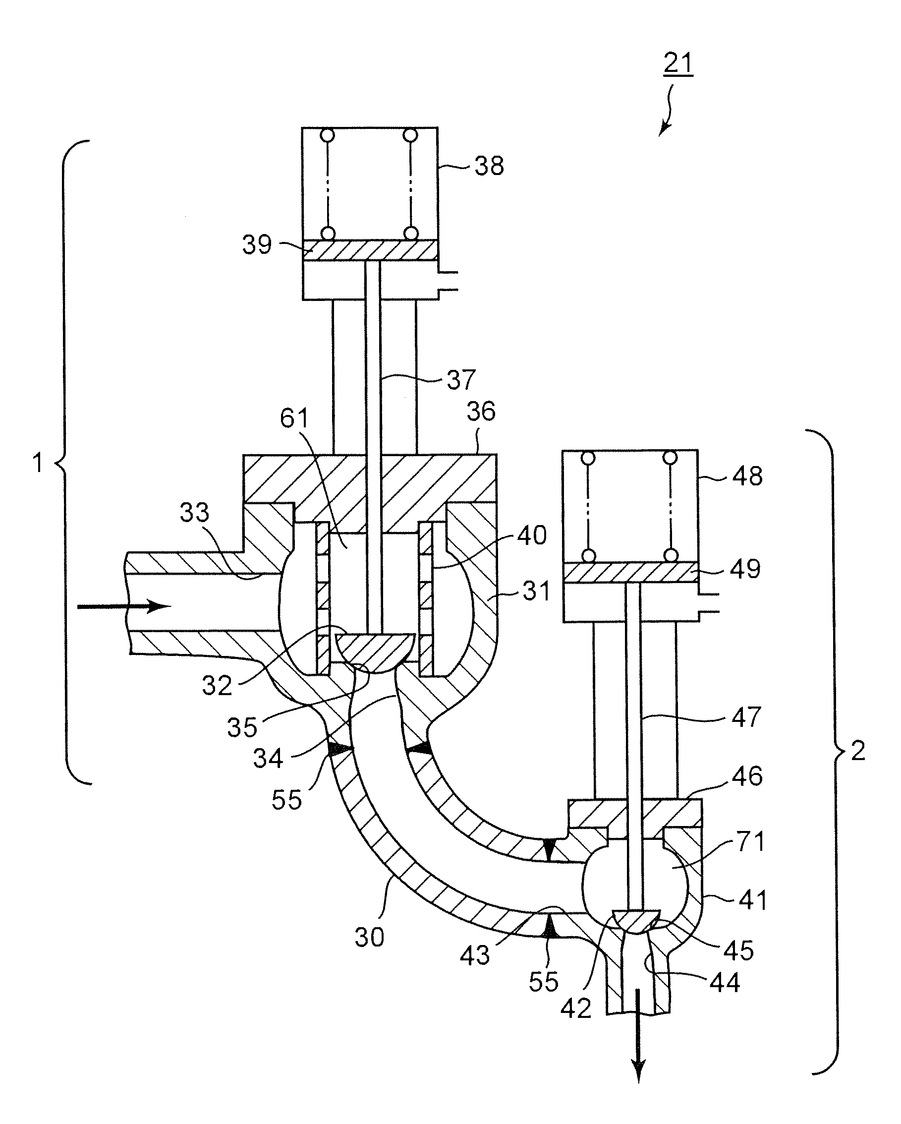
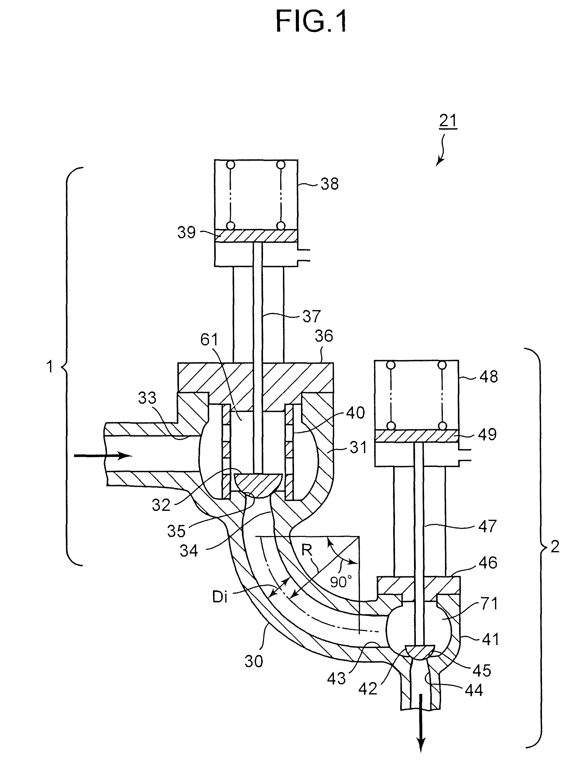
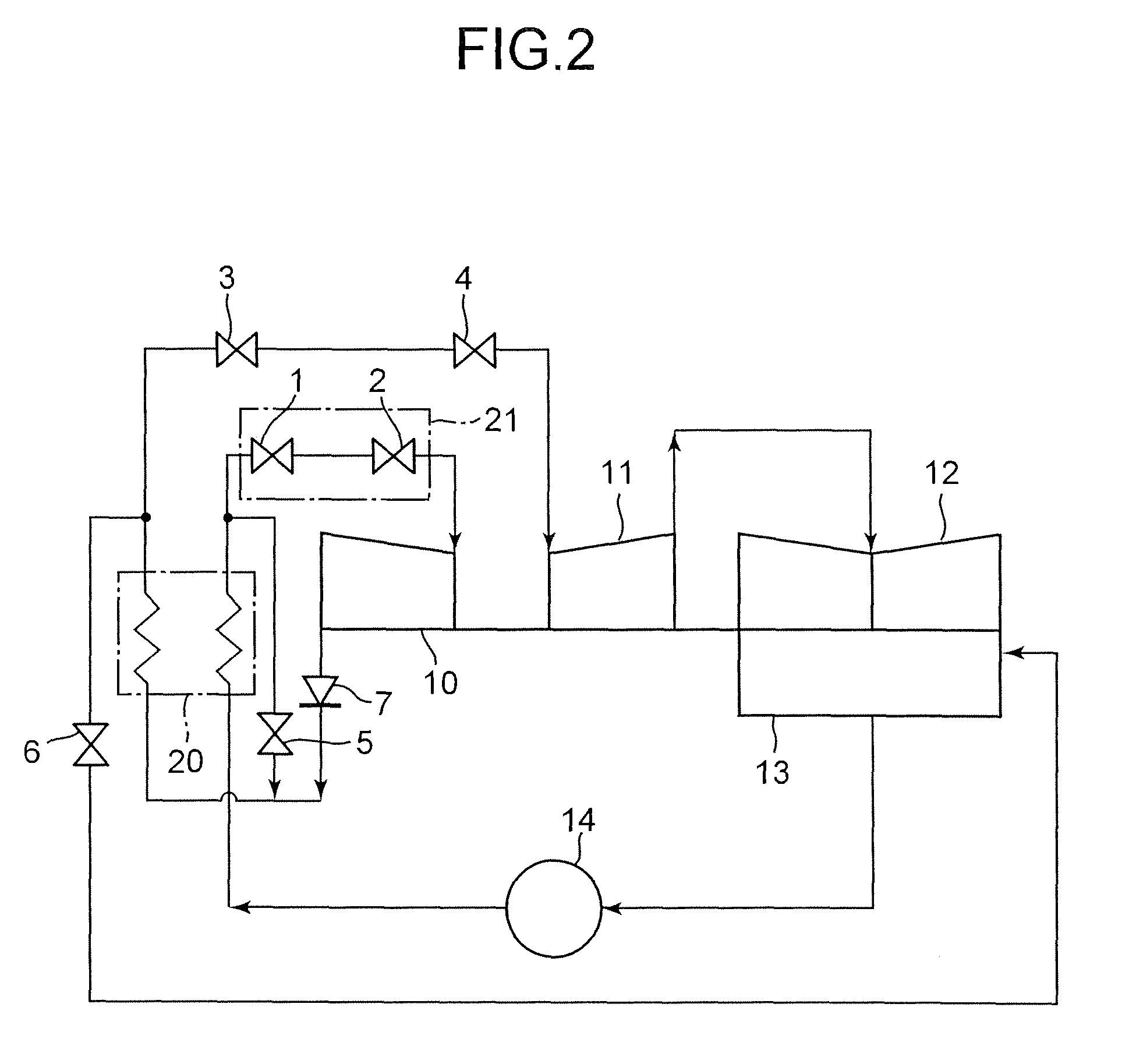
[0020]FIG. 1 is a vertical sectional view showing a first embodiment of a steam valve assembly according to the present invention. FIG. 2 is a system diagram showing a steam turbine plant that has the steam valve assembly according to the present invention.

[0021]The steam turbine plant is so designed that, as shown in FIG. 2, the steam flowing from a boiler 20 is supplied to a high-pressure steam turbine 10 via the steam valve assembly 21. The steam valve assembly 21 has a main-steam stop valve 1 and a steam control valve 2 arranged downstream of the main-steam stop valve 1. The steam that has done work in a high-pressure steam turbine 10 flows through a check valve 7 back into the boiler 20. In the boiler 20, the steam is heated again by a re-heater. The re-heated steam flows through a re-heated steam stop valve 3 and an intercept valve 4 into an intermediate-pressure steam turbine 11, and then to a low-pressure steam turbine 12. Thus, the steam performs work in both the intermedia...

second embodiment

[0038]FIG. 3 is a vertical sectional view showing a second embodiment of the steam valve assembly according to the present invention. The steam valve assembly 21 according to the second embodiment is almost identical in structure to the steam valve assembly according to the first embodiment. During the manufacture of the second embodiment, however, the main-steam stop valve 1, the steam control valve 2, and the intermediate flow path 30 are formed as separate units, each by means of forging or casting. Thereafter, the first casing 31 of the main-steam stop valve 1, the intermediate flow path 30, and the second casing 41 of the steam control valve 2 are connected by, for example, welding, at the junctions 55.

[0039]Fluid is known to flow in such a complex manner as explained in conjunction with the first embodiment. Centrifugal force is applied on that part of fluid, which flows along the center part of the intermediate flow path 30. This part of the fluid is pushed outward to the out...

third embodiment

[0045]FIG. 4 is a vertical sectional view showing a third embodiment of the steam valve assembly according to the present invention. This embodiment is a modification of the first embodiment. In the first embodiment, the intermediate flow path has one arcuate elbow having a bending angle of 90°. In the third embodiment, the intermediate flow path 30 is a combination of an arcuate elbow 50 and a straight flow-path part 51. The elbow 50 is connected to the outlet port (first outlet port) 34 of the main-steam stop valve 1 and has a bending angle of 45°. The straight flow-path part 51 is connected to the lower end of the elbow 50 and obliquely extends downward.

[0046]In this embodiment, the flow separation of the steam flowing in the elbow can be more suppressed, and the pressure loss can be further reduced. The ratio (R / Di) of the radius R of curvature of the elbow 50 to the inner diameter Di of the elbow 50 should preferably be 2 or more as in the first embodiment. Further, in this emb...


PUM


Abstract

A steam valve assembly has a main-steam stop valve, and a steam control valve connected downstream to the main-steam stop valve via an intermediate flow path. The two valves each has a casing having an inlet port directing horizontally, and an outlet port directing vertically. The valve bodies and the valve stems move up and down in the casings to open and close the flow paths in the valves. The intermediate flow path is configured to guide main steam from the outlet port of the main-steam stop valve in vertically downward direction to the inlet port of the steam control valve in horizontal direction.

Description

CROSS-REFERENCE TO RELATED APPLICATIONS[0001]This application is based upon and claims the benefits of priority from the prior Japanese Patent Applications No. 2007-332057, filed in the Japanese Patent Office on Dec. 25, 2007, the entire content of which is incorporated herein by reference.BACKGROUND OF THE INVENTION[0002]The present invention relates to a steam valve assembly having a main steam-stop valve and a steam control valve, and to a steam turbine plant that has the steam valve assembly.[0003]In a typical conventional steam turbine plant, the steam coming from the boiler is applied to the steam turbine through the steam valve assembly. The steam that has done work in the steam turbine is changed back to water in the condenser. The condensed water is then supplied by the water pump to the boiler. Water is thus circulated in the steam turbine plant. The steam valve assembly has a main-steam stop valve and a steam control valve that is arranged downstream of the main-steam sto...

Claims


Application Information

Patent Timeline
Patent Type & Authority Patents(United States)
IPC IPC(8): G05D16/06
CPCF01D1/00F01D17/145F05D2220/31Y10T137/87917F05D2250/312Y10T137/87121F05D2220/72F01D17/10F01K11/00
Inventor SHINDO, OSAMU
Owner KK TOSHIBA
Why Eureka
Try Eureka