
Ceramic porous membrane and ceramic filter

a ceramic filter and porous membrane technology, applied in the direction of membranes, filtration separation, separation processes, etc., can solve the problems of membrane peeling, the porous membrane formed on the fired base surface is generated by defects, and the membrane cannot be uniformly formed on the whole base surface, etc., to achieve less defects, reduce the number of membrane formation times, and reduce pressure loss

Inactive Publication Date: 2010-08-05
NGK INSULATORS LTD
View PDF11 Cites 6 Cited by
  • Summary
  • Abstract
  • Description
  • Claims
  • Application Information

AI Technical Summary

Benefits of technology

The present invention provides a ceramic porous membrane that can be formed on an ultrafiltration membrane with less membrane formation times and defects, and a high flux. The ceramic porous membrane is formed on the ultrafiltration membrane without substantially permeating its pores. An intermediate layer with a smaller pore size can be added between the ceramic porous membrane and the ultrafiltration membrane to further improve the performance of the membrane. The ceramic filter made with this membrane has a high separability, high flux, and high durability. The use of a titania membrane as the ultrafiltration membrane provides better resistance to acid, alkali, and water vapor, and reduces costs compared to a silica membrane.

Problems solved by technology

However, the hot coating process has a problem that the membrane cannot uniformly be formed on the whole base surface, and the membrane can be formed on the only outer surface of the tube base member.
On the other hand, in the filtering membrane formation process, during drying of the formed membrane, a solvent present in base pores sometimes flows out on a membrane side to cause membrane peeling.
As a result, there is a problem that a defect is generated in the porous membrane formed on the fired base surface.

Method used


Image

  • Ceramic porous membrane and ceramic filter
  • Ceramic porous membrane and ceramic filter
  • Ceramic porous membrane and ceramic filter

Examples


example 1

(1) Porous Base Member

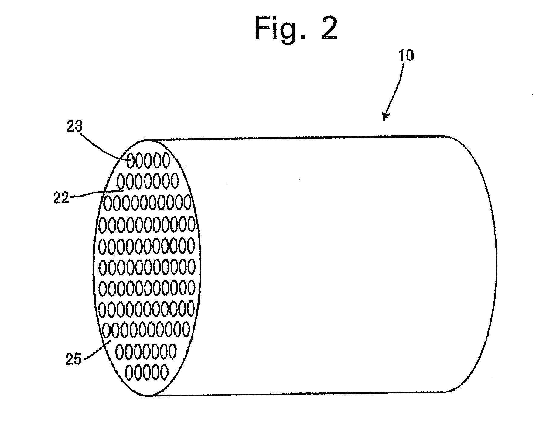
[0047]A material provided with an alumina membrane having an average pore diameter of 0.2 μm and having a monolith shape (an outer diameter of 30 mm, a cell inner diameter 3 mm×37 cells and a length of 500 mm) was used as a base member. It is to be noted that opposite end portions of the base member were sealed with glass. The average pore diameter of the base member was measured based on an air flow process described in ASTM F306.

(2) Titania Sol Liquid

[0048]Titanium isopropoxide was hydrolyzed in the presence of nitric acid to obtain a titania sol liquid. A sol particle diameter measured by a dynamic optical scattering process was 100 nm.

(3) Titania UF Membrane Formation

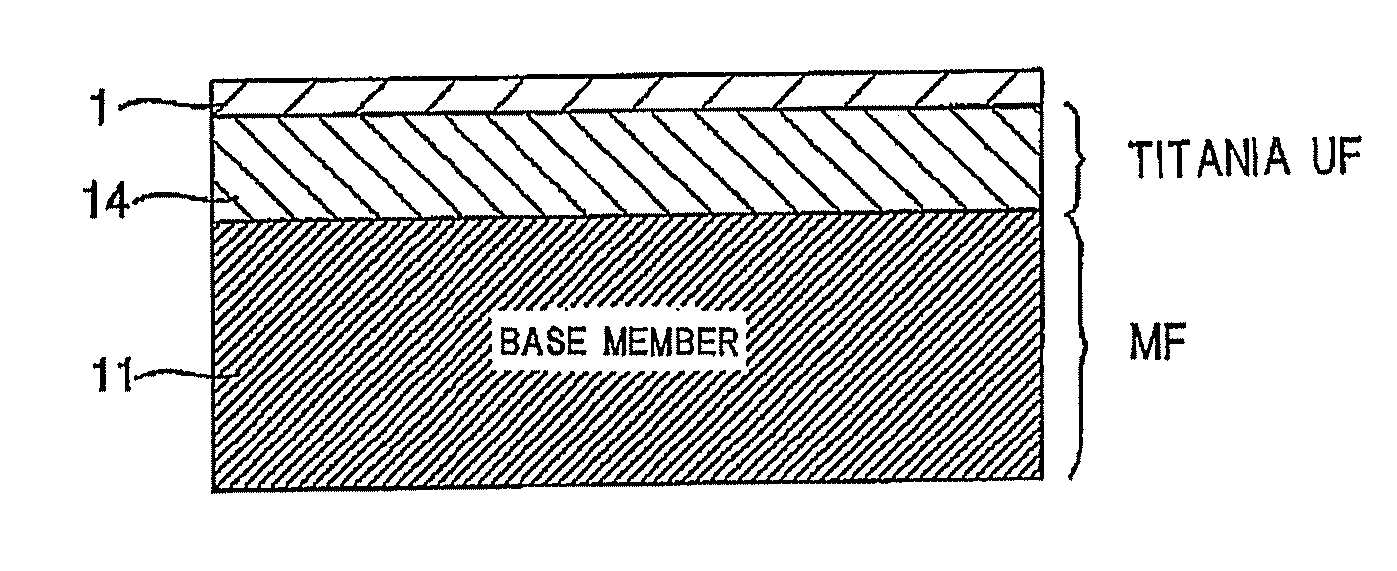
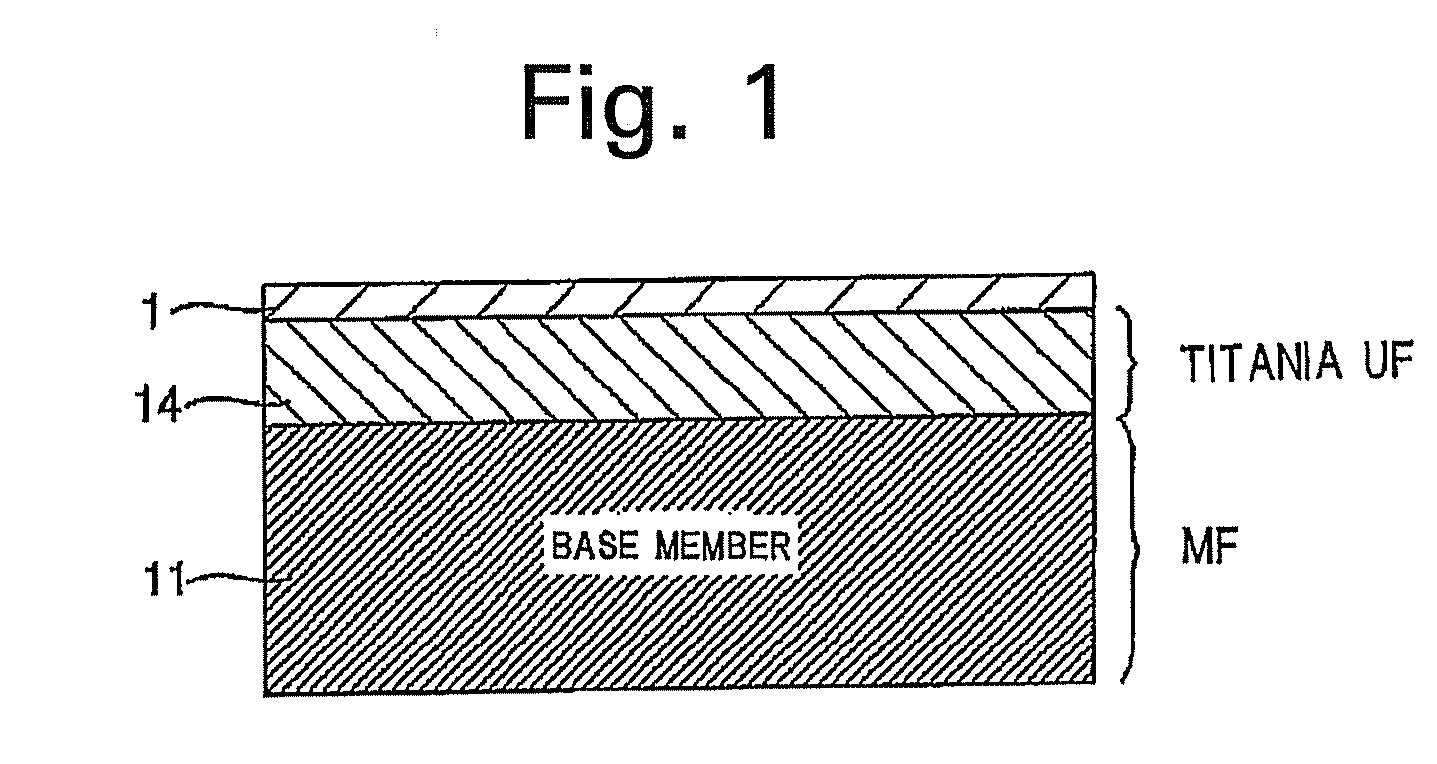
[0049]The titania sol liquid was diluted with water to obtain a sol liquid for membrane formation. The liquid was circulated through base cells to come in contact with the cells, whereby the membrane was formed in the cells.

(4) Drying, Firing

[0050]After a sample was dried, the sample was therma...

example 2

[0056]During titania UF preparation of (1) to (4) of Example 1, titania was not fired unlike (4), and used as a base member, and then silica membrane formation of (6) to (9) was performed.

example 3

[0057]During titania UF preparation of (1) to (4) of Example 1, titania was fired at 300° C. in (4), and then silica membrane formation of (6) to (9) was performed.


PUM

PropertyMeasurementUnit
pore diameteraaaaaaaaaa
weight ratioaaaaaaaaaa

Abstract

There are disclosed a ceramic porous membrane formed with less membrane formation times and having less defects, a small and uniform thickness and a high flux, and a ceramic filter. A silica membrane is formed on a titania UF membrane as an ultrafiltration membrane (a UF membrane) formed on a porous base member which is a microfiltration membrane (also referred to as an MF membrane) and having an average pore diameter smaller than that of the porous base member, and the silica membrane has an average pore diameter smaller than that of the titania UF membrane, and does not substantially permeates the titania UF membrane.

Description

CROSS REFERENCE TO RELATED APPLICATION[0001]This application is a continuation of U.S. application Ser. No. 11 / 850,693, filed Sep. 6, 2007, the entirety of which is incorporated herein by reference.FIELD OF THE INVENTION[0002]The present invention relates to a ceramic porous membrane and a ceramic filter. More particularly, it relates to a ceramic porous membrane having less defects and having a small and uniform thickness, and a ceramic filter.BACKGROUND OF THE INVENTION[0003]Heretofore, various methods of forming a ceramic porous membrane on a porous base member have been known. For example, a hot coating process is known (see Non-Patent Document 1). This is a method of rubbing a tube base member with cloth containing a silica sol to apply the silica sol and thereby form a porous membrane on an outer surface of the heated tube base member.[0004]A method of forming a porous membrane on an inner surface of a porous base member having a tubular shape or a cylindrical lotus-root-like ...

Claims


Application Information

Patent Timeline
Patent Type & Authority Applications(United States)
IPC IPC(8): C02F1/44
CPCB01D67/0048B01D69/12B01D2325/02B01D71/02B01D67/0095B01D71/024B01D2325/0283B01D69/1213B01D71/0213
Inventor ISOMURA, MANABUHISHIKI, TATSUYAWADA, ICHIRO
Owner NGK INSULATORS LTD
Learn More