

Method of manufacturing ceramic porous membrane
Inactive Publication Date: 2008-03-20
NGK INSULATORS LTD
View PDF5 Cites 8 Cited by
- Summary
- Abstract
- Description
- Claims
- Application Information
AI Technical Summary
Benefits of technology
[0013] The present invention has been developed in view of the above-mentioned problem of the conventional technology, and an object thereof is to provide a method of manufacturing a ceramic porous membrane in which a uniform porous membrane having less coarse and large pores and less defects and having a small thickness can be obtained with less membrane formation times.
[0014] As a result of intensive investigation of the present inventors, it has been found that the above-mentioned problem of the conventional technology can be solved by performing vacuum suction from a secondary side (the side of a surface on which any membrane is not formed) of a porous base member after a ceramic sol liquid is completely discharged, and the present invention has been completed.
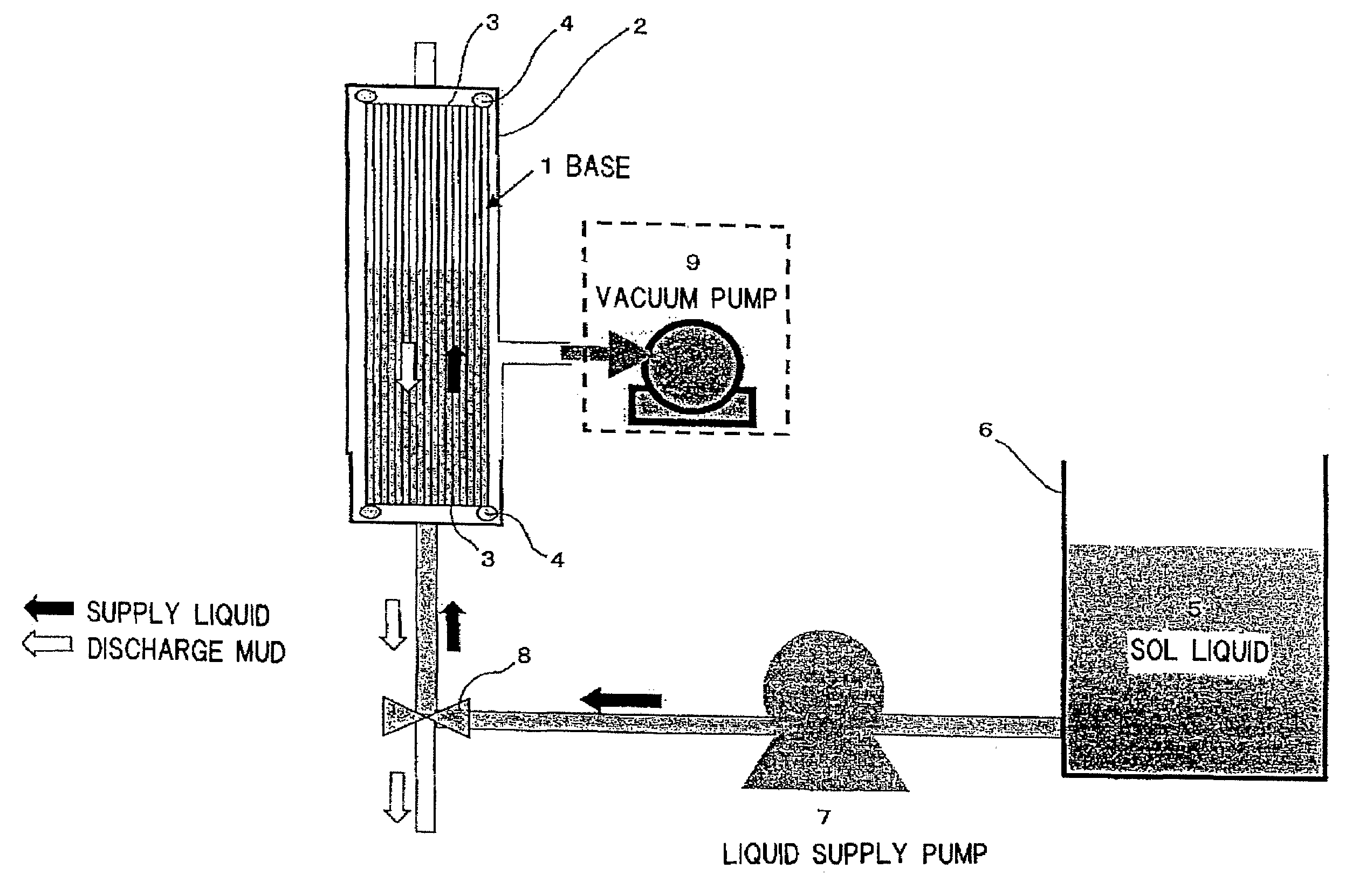
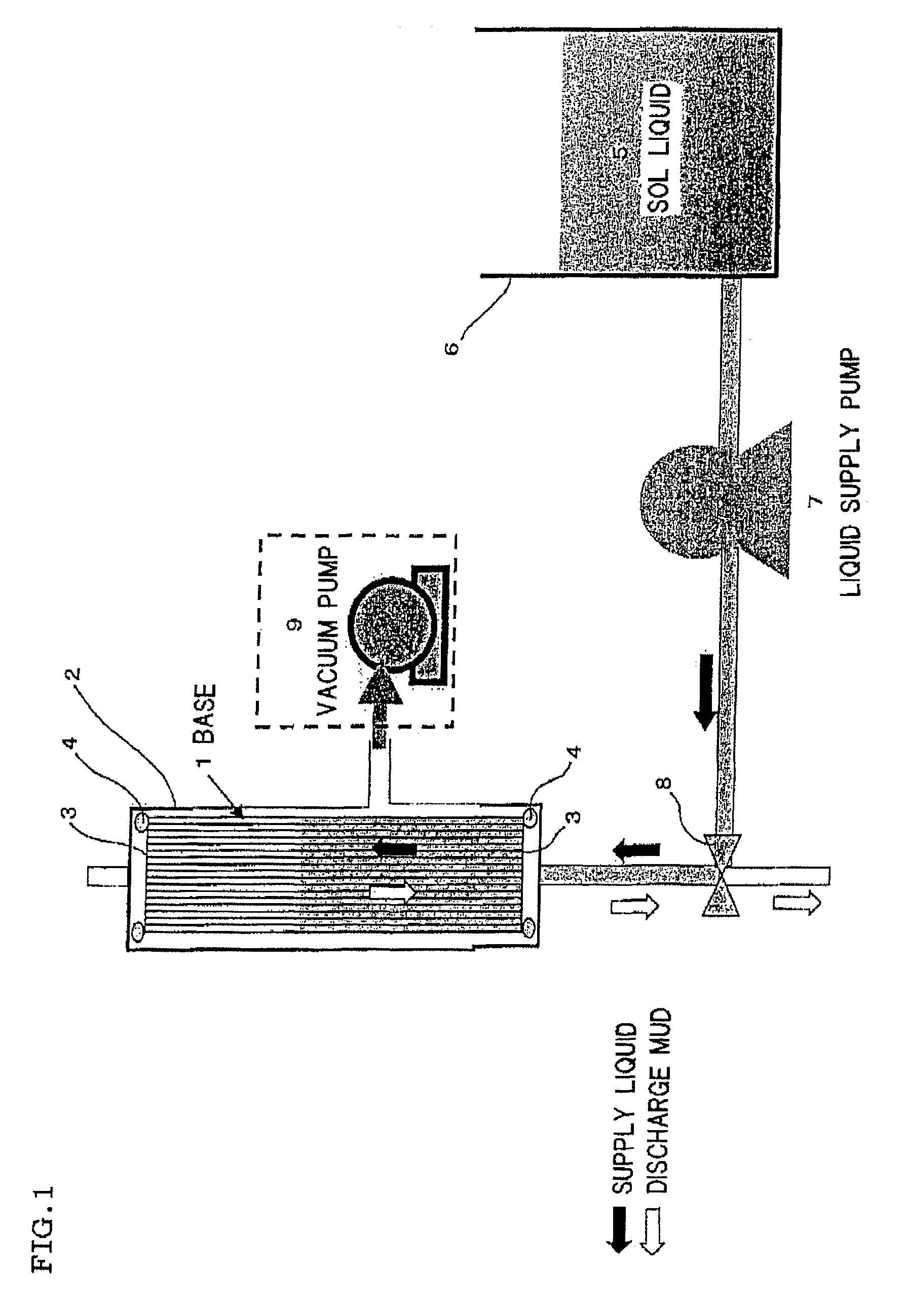
[0015] That is, according to the present invention, there is provided a method of manufacturing a ceramic porous membrane in which the ceramic porous membrane is formed on inner wall surfaces of through holes of a cylindrical or lotus root-like porous base member, the method comprising: installing the porous base member so that the through holes of the base member are arranged in a vertical direction; supplying, to the inner wall surface of the porous base member, a ceramic sol liquid having a temperature difference of 50° C. or less between the ceramic sol liquid and the porous base member; stopping the liquid supply at a stage where the ceramic sol liquid is spread all over the inner wall surface of the porous base member to discharge the ceramic sol liquid from the downside of the porous base member; and creating a pressure difference so that a pressure on the side of an outer peripheral surface of the porous base member is lower than that on the side of the inner wall surface of the porous base member after the discharge of the ceramic sol liquid is completed.
[0018] In the method of manufacturing the ceramic porous membrane of the present invention, to avoid particle diameter changes of sol particles of the sol liquid, it is preferable that the ceramic sol liquid is at 100° C. or less. The ceramic sol liquid and the porous base member may be heated at 100° C. or less so that the temperature difference therebetween is 50° C. or less, preferably 10° C. or less. In this case, as long as the temperature difference between the porous base member and the ceramic sol liquid is 50° C. or less, the temperature of either the porous base member or the ceramic sol liquid may be higher. Furthermore, in the present invention, from the operational viewpoints, it is preferable that a manner of creating the pressure difference is a manner of performing vacuum suction from the outer peripheral surface (a secondary side) of the porous base member.
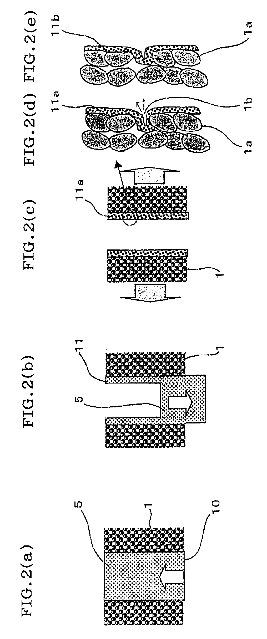
[0019] According to the present invention, since the porous base member is not pulled up but the ceramic sol liquid is supplied and discharged, the present invention can be applied to a large-sized porous base member. Moreover, after discharging the ceramic sol liquid, the pressure difference is created by the vacuum suction or the like so that the pressure on the side of the outer peripheral surface of the porous base member is lower than that on the side of the inner wall surface of the porous base member. Therefore, since the sol liquid preferentially permeates a large defect portion of the porous base member, the defect portion can be repaired with less membrane formation times (thin membranes). As a result, the method of manufacturing the ceramic porous membrane according to the present invention has an excellent effect that a porous membrane having an average pore diameter level of 0.1 to 100 nm and having less coarse and large pores and less defects can be obtained.
Problems solved by technology
However, the hot coating process has a problem that the membrane cannot uniformly be formed on the whole base surface, and the process cannot be applied to the inside of the monolith base having the tubular or cylindrical lotus root-like shape.
As a result, there is a problem that a defect is generated in the porous membrane formed on the fired base surface.
Moreover, in the dipping process, the problem generated in the filtering membrane formation process is not generated, but it is difficult to pull up a submerged long and large base member.
Therefore, there is difficulty in applying the process to a base member having a large membrane area.
This results in a problem that the defects are generated in the porous membrane formed on the fired base surface.
Method used
View moreImage
Smart ImageViewing Examples

Examples
example 2
[0068] As a material of a porous base member, the same material as that of Example 1 was used, and the porous base member was prepared by the same method as that of Example 1 except that a sol liquid B was used as a sol liquid and both of the sol liquid and the base member had room temperature (20° C.)
example 3
[0069] As a material of a porous base member, the same material as that of Example 2 was used, and the porous base member was prepared by the same method as that of Example 2 except that a sol liquid C was used as a sol liquid.
Login to View More PUM
| Property | Measurement | Unit |
|---|---|---|
| Temperature | aaaaa | aaaaa |
| Temperature | aaaaa | aaaaa |
| Pore size | aaaaa | aaaaa |
Abstract
A method of manufacturing a ceramic porous membrane on inner wall surfaces of through holes of a porous base member. The through holes of the base member are arranged in a vertical direction, a ceramic sol liquid having a temperature difference of 50° C. or less between the sol liquid and the base member is supplied to the inner wall surface of the base member, the liquid supply is stopped when the sol liquid exceeds an upper end portion of the base member, and then the sol liquid is extracted from the bottom of the base member. After the sol liquid is completely extracted, a pressure difference is created so that a pressure on the side of an outer peripheral surface of the base member is lower than that on the side of the inner wall surface of the base member.
Description
TECHNICAL FIELD [0001] The present invention relates to a method of manufacturing a ceramic porous membrane. More particularly, it relates to a method of manufacturing a ceramic porous membrane in which a uniform porous membrane having less large and coarse pores and less defects and having a small membrane thickness can be formed on an inner surface of a porous base member with less membrane formation times. BACKGROUND ART [0002] Heretofore, various methods of forming a ceramic porous membrane on each porous base member have been known. [0003] For example, a hot coating process is known (see Non-Patent Document 1). This is a method of rubbing a tube base member with a cloth containing a silica sol to apply the silica sol thereto and thereby form a porous membrane on an outer surface of the tube base member heated at about 200° C. In addition, a method of forming a sol into a thin membrane on a substrate of a ceramic or the like by a dipping process is also known (see Non-Patent Doc...
Claims
Login to View More Application Information
Patent Timeline
 IPC IPC(8): B05D5/00
CPCB01D63/066B01D67/0048C04B2111/00801C04B41/87C04B41/4537B01D69/04B01D69/046B01D71/024B01D71/027B01D2323/42C04B35/46C04B35/624C04B41/009C04B41/4515C04B41/457C04B41/4582C04B41/5041C04B41/5035C04B35/10C04B35/00C04B35/185C04B35/48C04B38/00
InventorTANAKA, KEI
OwnerNGK INSULATORS LTD