Gas burner for dryer
- Summary
- Abstract
- Description
- Claims
- Application Information
AI Technical Summary
Benefits of technology
Problems solved by technology
Method used
Image
Examples
first embodiment
[0096]Next, FIG. 5 illustrates a second preferred embodiment of the present invention. The embodiment in FIG. 5 has a flame holder 160 fitted to an outlet side of the mixing passage 41 of the mixing tube 40 different from the
[0097]That is, the flame holder 160 has a central circular flame hole 162 with a diameter, and a plurality of fan shaped flame holes 164 around the circular flame hole 162 each with a width enlarged in a radial direction. The fan shaped flame holes 164 are separate from the circular flame hole 162.
[0098]FIG. 6 illustrates a third preferred embodiment of the present invention. In the embodiment shown in FIG. 6, the flame holder 260 fitted to a downstream of the mixing passage 41 of the mixing tube 40 has a plurality of same diametered circular flame holes 262 of forms of pass through holes for spraying gas mixed with primary air as the gas flows through the mixing passage 41. When the gas is sprayed to outside of the mixing passage 41, the plurality of circular f...
third embodiment
[0100]The operation of the foregoing first to third embodiment of the present invention will be explained, with reference to the embodiment shown in FIG. 4.
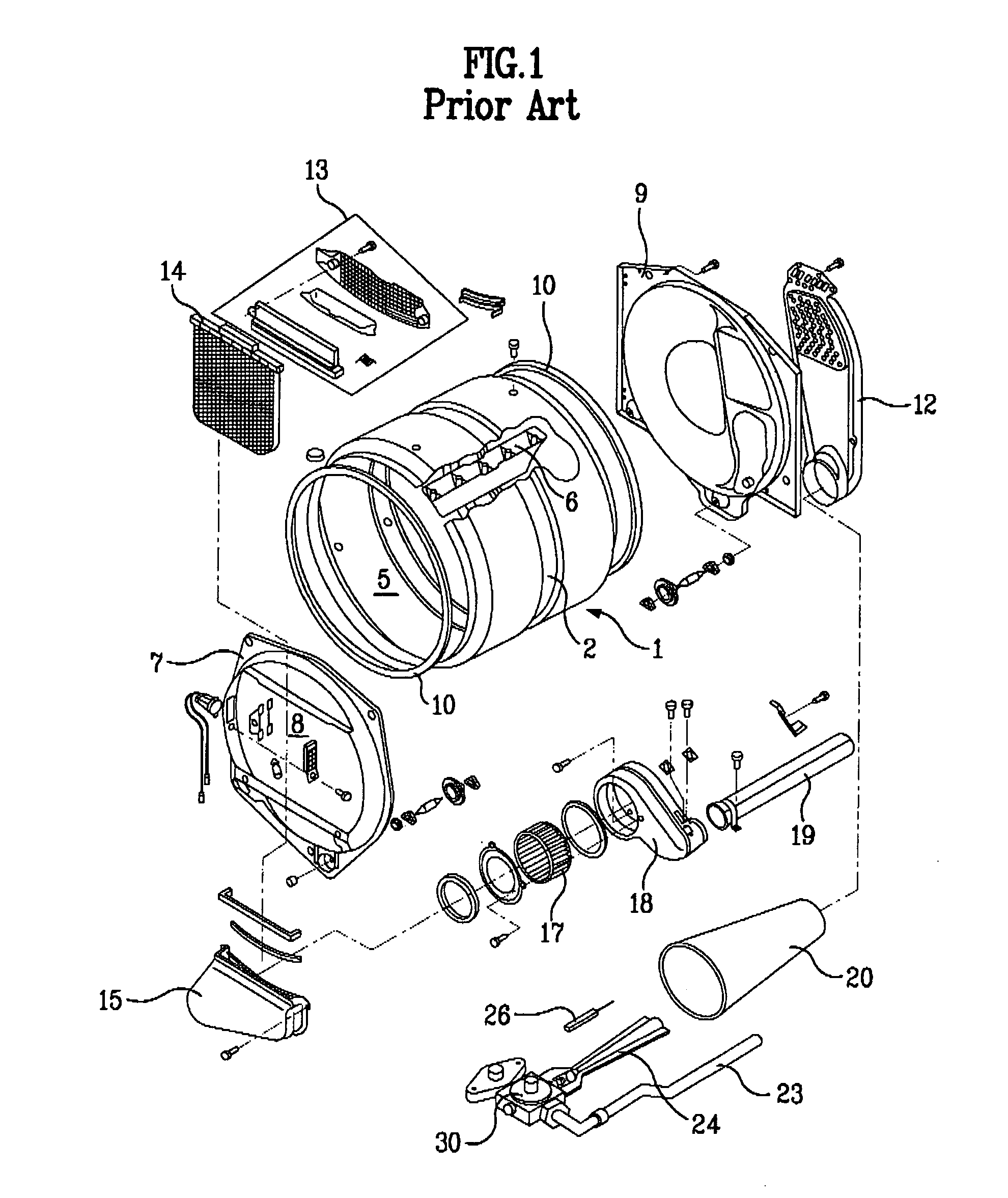
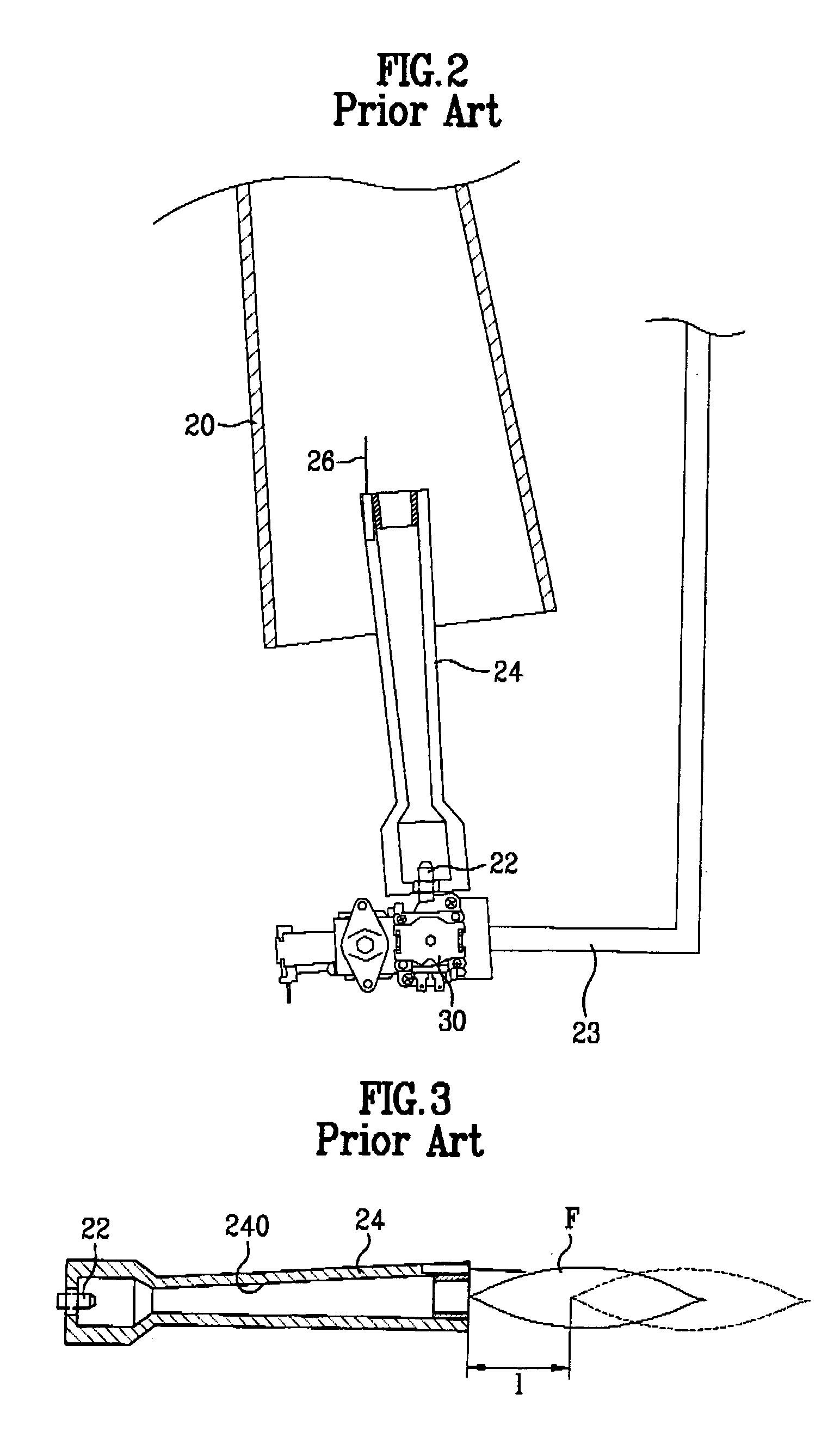
[0101]For having a drying process progressed in a dryer, it is required to elevate a temperature of air introduced into the drying chamber 5 as the gas is burned. For this, burning gas is sprayed into the mixing tube 24 through the gas nozzle 22.
[0102]Along with the gas, primary air is introduced into the mixing tube 24. Accordingly, the gas and the primary air are mixed, and flow along the passage inside of the mixing tube 24.
[0103]Then, the gas (i.e., a mixed gas) mixed with the primary air as the gas and the primary air flow along the inside passage of the mixing tube 24 is split, and sprayed through the flame holes 62 or 64 of the flame holder 60 fitted to the outlet side of the mixing tube 24. The mixed gas sprayed thus is ignited as the mixed gas receives heat from the igniter 50 provided adjacent to the flame holder 60.
[01...
fourth embodiment
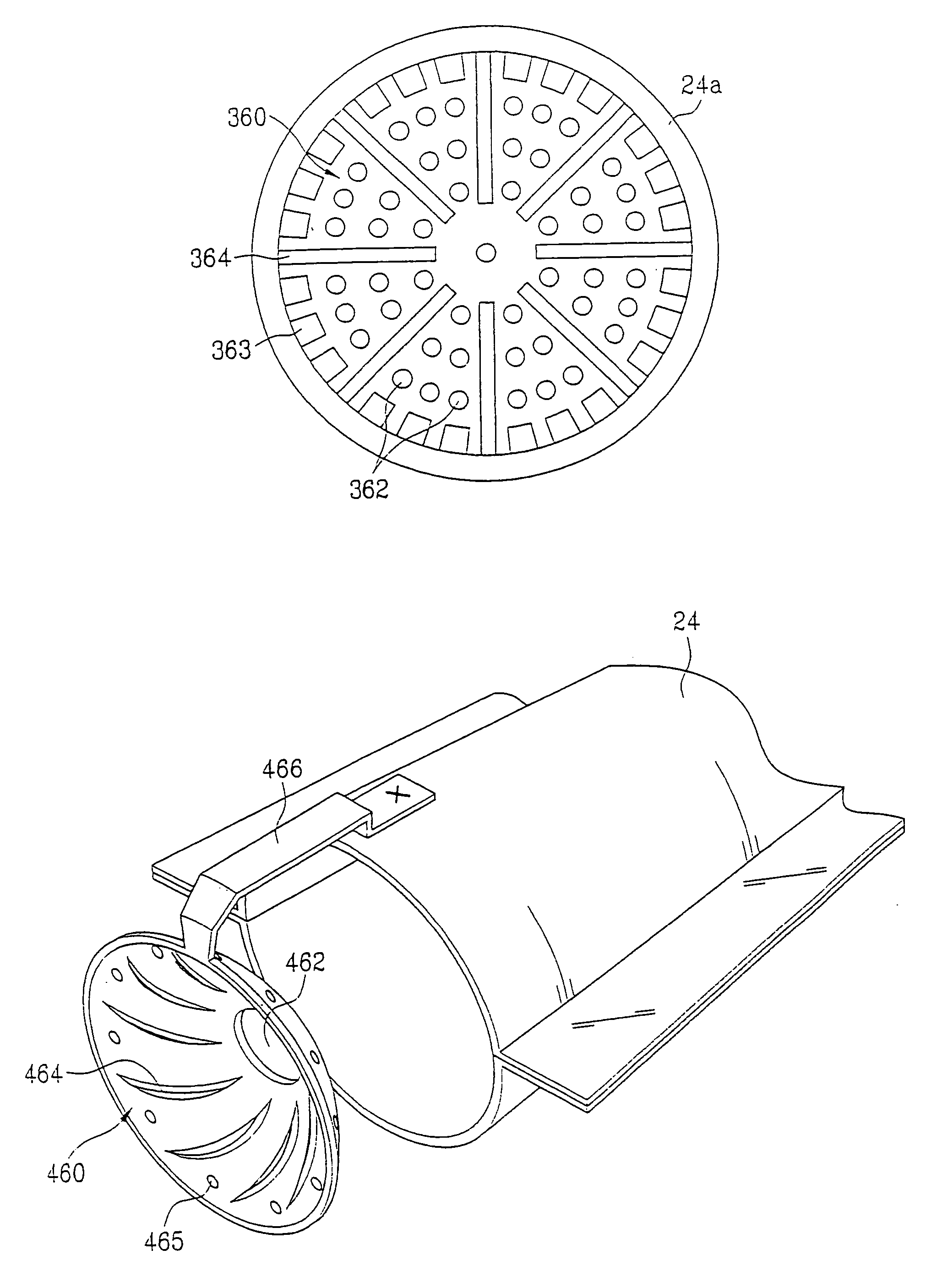
[0127]the present invention will be explained, with reference to the embodiment shown in FIGS. 7–9.
[0128]For having a drying process progressed in a dryer, it is required to elevate a temperature of air introduced into the drying chamber 5 as the gas is burned. For this, burning gas is sprayed into the mixing tube 24 through the gas nozzle 22.
[0129]Along with the gas, primary air is introduced into the mixing tube 24. Accordingly, the gas and the primary air are mixed, and flow along the passage inside of the mixing tube 24.
[0130]Then, the gas (i.e., a mixed gas) mixed with the primary air as the gas and the primary air flow along the inside passage of the mixing tube 24 is split, and sprayed through the flame holes 362, 363, or 364 of the flame holder 360 fitted to the outlet side of the mixing tube 24. The mixed gas sprayed thus is ignited as the mixed gas receives heat from the igniter 50 provided adjacent to the flame holder 360.
[0131]Then, drying hot air is produced continuousl...
PUM
 Abstract
Description
Claims
Application Information
 - R&D
- Intellectual Property
- Life Sciences
- Materials
- Tech Scout
- Unparalleled Data Quality
- Higher Quality Content
- 60% Fewer Hallucinations
Browse by: Latest US Patents, China's latest patents, Technical Efficacy Thesaurus, Application Domain, Technology Topic, Popular Technical Reports.
© 2025 PatSnap. All rights reserved.Legal|Privacy policy|Modern Slavery Act Transparency Statement|Sitemap|About US| Contact US: help@patsnap.com


