Optical fiber sensor based on retro-reflective fiber bragg gratings

Inactive Publication Date: 2005-10-20
HER MAJESTY THE QUEEN & RIGHT OF CANADA REPRESENTED BY THE MIN OF IND THROUGH THE COMM RES CENT
View PDF0 Cites 22 Cited by
  • Summary
  • Abstract
  • Description
  • Claims
  • Application Information

AI Technical Summary

Benefits of technology

[0020] There are three broad aspects to this invention. An optical waveguide sensor is provided that may conveniently be made of a rod of a crystalline material such as sapphire, having a glass transition temperature substantially above that of silica, and which has written into the core thereof, a retro-reflective grating that is suitable as a sensor in relatively high temperature environments; when the rod consists entirely of a core material having no cladding, which is typically the case with a sapphire optical fiber, the grating can be used as a chemical sensor sensing information about the surrounding environment. The crystalline material having the grating written therein is also useful as a mechanical strain sensor or a temperature sensor. In all of these embodiments, using a material with a high glass transition temperature, for example greater than 1300° C., allows the se

Problems solved by technology

This obviates problems associated with conventiona

Method used


Image

  • Optical fiber sensor based on retro-reflective fiber bragg gratings
  • Optical fiber sensor based on retro-reflective fiber bragg gratings
  • Optical fiber sensor based on retro-reflective fiber bragg gratings

Examples


Example

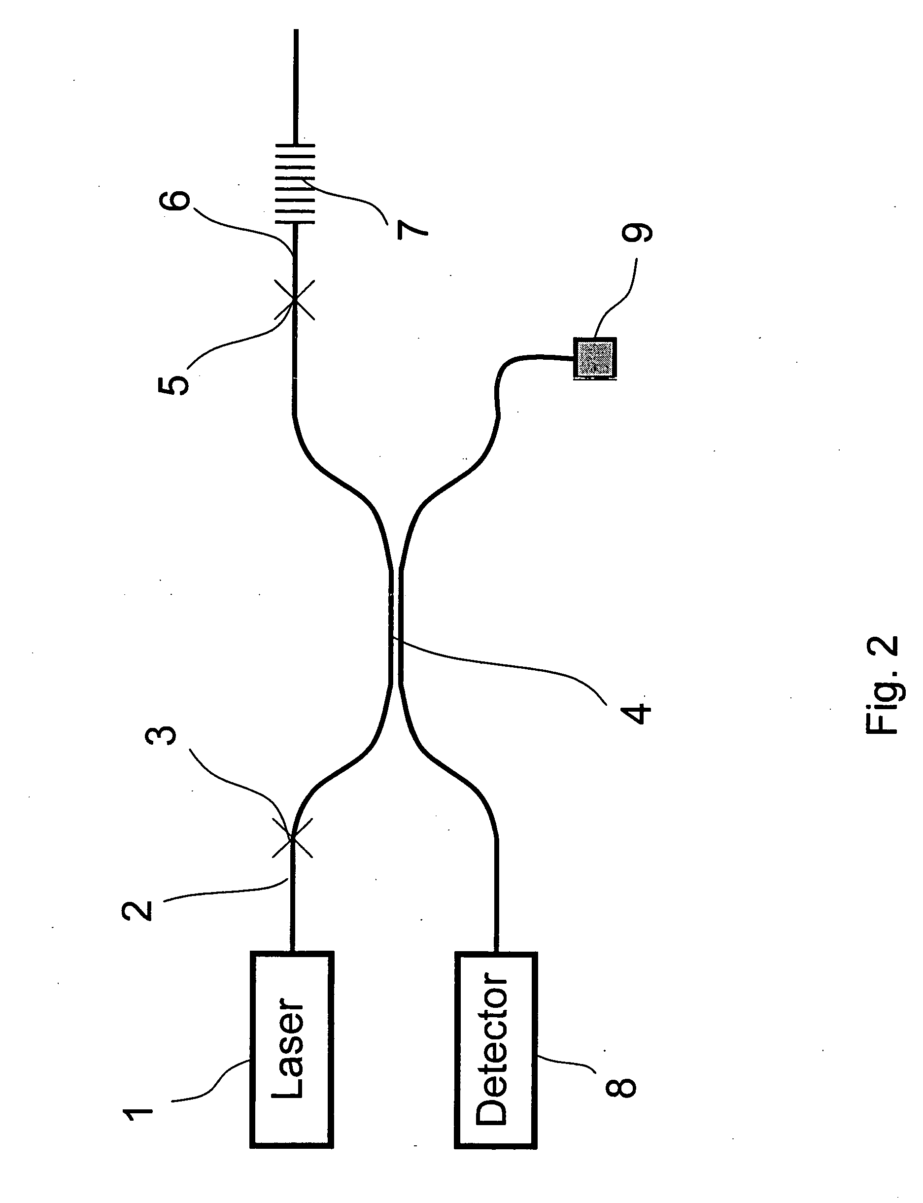
[0070] Referring to FIG. 2, light generated by a laser diode or tunable laser 1 is coupled into single mode fiber 2. Light coupled into fiber 2 couples into the input arm of the 50-50 multimode coupler 4 through the single to multimode fiber splice 3. The coupler 4 splits the signal in two with each signal at 50% of the energy. One portion of the beam propagates along the fiber which is terminated with index matching gel 9 and is lost. The other portion propagates to the multimode fibre-sapphire fibre splice 5 and then into the sapphire fibre 6. The light then interacts with the Bragg grating 7 and a portion of the light is resonantly coupled into back reflecting modes by the grating 7. The back reflected modes couple return along the incident path of 6, 5, and 4 to be split again with each reflected signal 50% of the original reflected signal, one portion returning to the laser source 1, the other to the detector 8. In the preferred embodiment the detector is an optical spectrum an...


PUM


Abstract

A retro-reflective sensor for sensing mechanical, chemical or temperature related information, is disclosed. The sensor is formed of an optical waveguide suitable for use in-situ in a high temperature environment having a Bragg grating written into a core region thereof with short-pulsed electromagnetic radiation, said optical waveguide having a glass transition temperature substantially higher than that of silica. Preferably the sensor is written into a length of sapphire fiber or within a zirconium waveguide. Preferably the pulse duration of the short pulsed electromagnetic radiation is less than 500 picoseconds.

Description

CROSS-REFERENCE TO RELATED APPLICATIONS [0001] This application claims priority of application Ser. Nos. 10 / 639,486 filed Aug. 13, 2003; Ser. No. 10 / 803,890 filed Mar. 19, 2004; 60 / 456,184 filed Mar. 21, 2003; 60 / 545,949 filed Feb. 20, 2004; 60 / 616,838 filed Oct. 8, 2004; 60 / 561,882 filed Apr. 14, 2004; 60 / 634, 547 filed Dec. 10, 2004; Canadian Applications Nos: 2,436,499 filed Aug. 1, 2003 and 2,461,368 filed Mar. 19, 2004; European Application Nos: 03405845.3 filed Nov. 26, 2003 and 04405172.0 filed Mar. 22, 2004.FIELD OF THE INVENTION [0002] The present invention relates to a sensing apparatus and method for measurement of pressure, strain, temperature, or displacement or index of refraction of a high temperature environment and more particularly to a fiber Bragg grating sensor inscribed therein capable of measuring temperature, strains, and environment at temperatures over the glass transition temperature for silica, for example at or above 1300° C. and in some instances above 2...

Claims


Application Information

Patent Timeline
IPC IPC(8): G02B6/02G02B6/34
CPCG02B6/021G02B6/02147G02B6/02142G02B6/02133
Inventor MIHAILOV, STEPHEN J.GROBNIC, DANSMELSER, CHRISTOPHERWALKER, ROBERTLU, PINGDING, HUIMINHENDERSON, GEORGEDAI, XIAOLI
Owner HER MAJESTY THE QUEEN & RIGHT OF CANADA REPRESENTED BY THE MIN OF IND THROUGH THE COMM RES CENT
Why Eureka
Try Eureka