Two-stage compression rotary compressor

a rotary compressor and compression technology, applied in the direction of positive displacement liquid engine, lighting and heating apparatus, liquid fuel engine, etc., can solve the problems of significant pressure loss and efficiency reduction

Inactive Publication Date: 2009-04-02
FUJITSU GENERAL LTD
View PDF1 Cites 6 Cited by
  • Summary
  • Abstract
  • Description
  • Claims
  • Application Information

AI Technical Summary

Benefits of technology

[0010]It is an object of the present invention to at least partially solve the problems in the conventional technology.

Problems solved by technology

Consequently, there is significant loss of pressure, and decreased efficiency.

Method used


Image

  • Two-stage compression rotary compressor
  • Two-stage compression rotary compressor
  • Two-stage compression rotary compressor

Examples


Embodiment Construction

[0021]Exemplary embodiments of a two-stage compression rotary compressor according to the present invention are described below with reference to the accompanying drawing. Although the invention has been described with respect to a specific embodiment for a complete and clear disclosure, the appended claims are not to be thus limited but are to be construed as embodying all modifications and alternative constructions that may occur to one skilled in the art which fairly fall within the basic teaching herein set forth. The constituent elements in the embodiment described can be easily envisioned by those skilled in the art or can be virtually the same as described here.

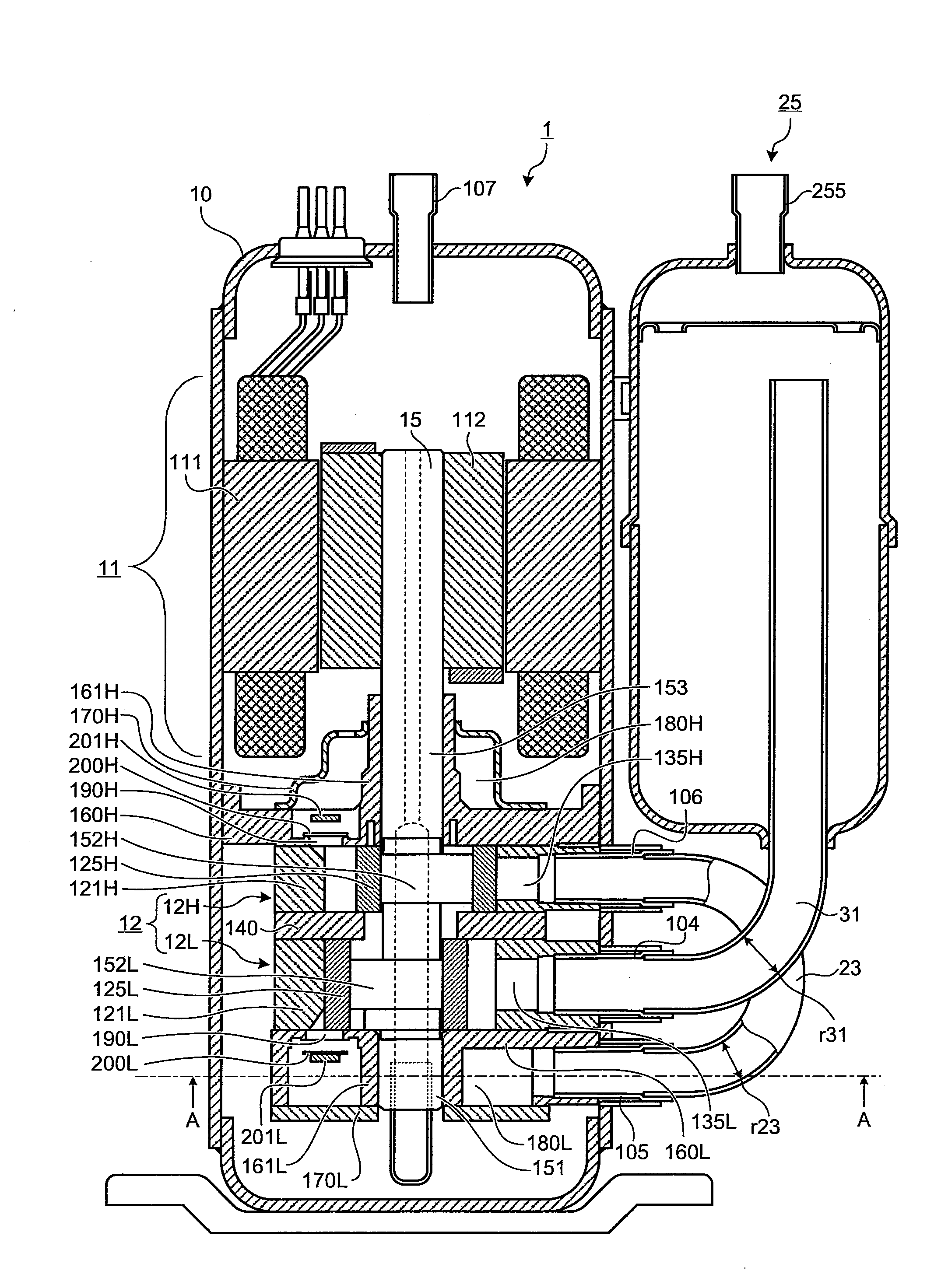
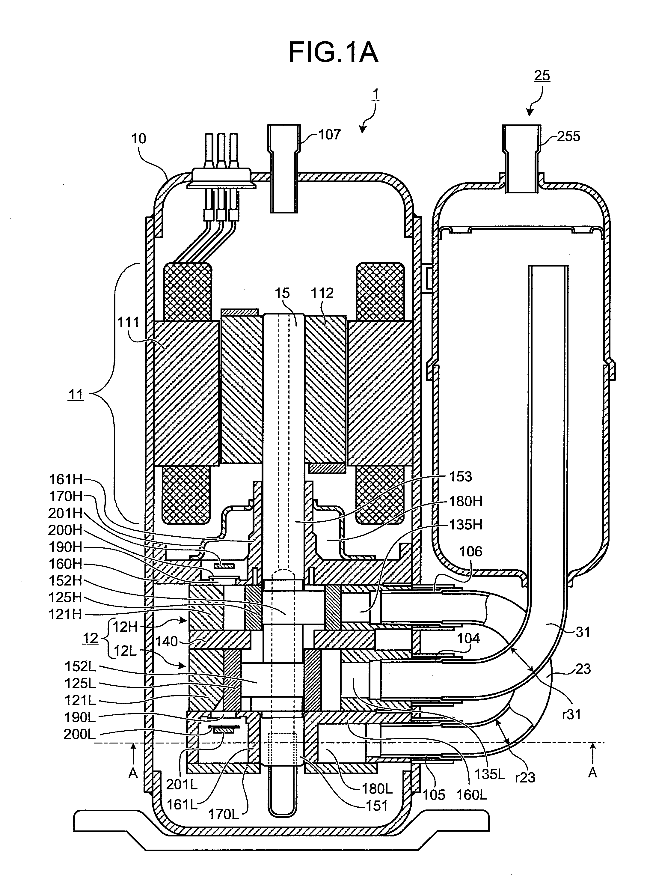
[0022]FIG. 1A is a cross-sectional view of a two-stage compression rotary compressor 1 according to a first embodiment of the present invention. The two-stage compression rotary compressor 1 includes a cylindrical sealed housing 10 disposed vertically with a compressing section 12 and a motor 11 that drives the compres...


PUM


Abstract

A two-stage compression rotary compressor is provided that includes a low-stage compressing section and a high-stage compressing section housed within a cylindrical sealed housing oriented vertically, a low-stage suction pipe that is connected to a suction side of the low-stage compressing section and sucks in a low-pressure refrigerant, a low-stage discharge pipe the is connected to a discharge side of the low-stage compressing section and discharges the refrigerant from the low-stage to outside of the sealed housing, a high-stage suction pipe that is connected to a suction side of the high-stage compressing section and sucks in the refrigerant discharged from the low-stage, a low-pressure connecting pipe that connects the low-stage suction pipe and an accumulator, and guides the refrigerant inside the accumulator to a suction side of a low-stage compressing section, and an intermediate connecting pipe that connects the low-stage discharge pipe and the high-stage suction pipe, wherein an inner diameter of the lower-stage connecting pipe is larger than an inner diameter of the intermediate connecting pipe.

Description

BACKGROUND OF THE INVENTION[0001]1. Field of the Invention[0002]The present invention relates to a two-stage compression rotary compressor.[0003]2. Description of the Related Art[0004]A two-stage compression rotary compressor generally includes a low-stage compressing section and a high-stage compressing section housed within a sealed housing, a motor that drives the low-stage compressing section and the high-stage compressing section, and an accumulator provided laterally to the compressor main unit.[0005]The sealed housing has a first through-hole, a second through-hole, and a third through-hole thereon, and includes a low-stage suction pipe connected to the suction side of the low-stage compressing section through the second through-hole to suck in a low-pressure Ps refrigerant gas.[0006]The sealed housing also includes a low-stage discharge pipe connected to the discharge side of the low-stage compressing section through the first through-hole; and a high-stage suction pipe conn...

Claims


Application Information

Patent Timeline
Patent Type & Authority Applications(United States)
IPC IPC(8): F04C23/00F04C28/26F25B1/10
CPCF04C18/3564F04C23/008F04C23/001
Inventor MOROZUMI, NAOYAUEDA, KENSHI
Owner FUJITSU GENERAL LTD
Why Eureka
Try Eureka