
Iron golf club head

a golf club and golf club technology, applied in golf clubs, sport apparatus, golf, etc., can solve the problems of insufficient difficulty in aligning the face plate with etc., to facilitate the alignment of the face plate and improve the connection strength between the heel side and the head main body.

Inactive Publication Date: 2011-09-06
BRIDGESTONE SPORTS
View PDF59 Cites 88 Cited by
  • Summary
  • Abstract
  • Description
  • Claims
  • Application Information

AI Technical Summary

Benefits of technology

This configuration simplifies alignment, increases connection strength, and enhances ball speed and repulsion performance, particularly for long irons, by ensuring a flush connection and distributing weight effectively.

Problems solved by technology

However, it is difficult to align the face plate with the head main body only by abutting the end face of the face plate on the heel side against the end face of the head main body on the heel side.
In addition, the connection strength of the face plate on the heel side and the head main body may become insufficient.

Method used


Image

  • Iron golf club head
  • Iron golf club head
  • Iron golf club head

Examples


Embodiment Construction

[0019]Preferred embodiments of the present invention will now be described in detail in accordance with the accompanying drawings.

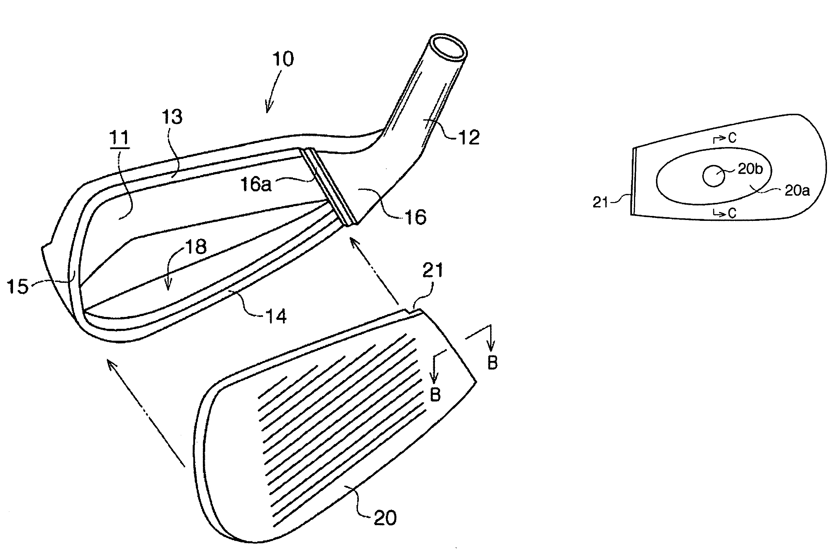
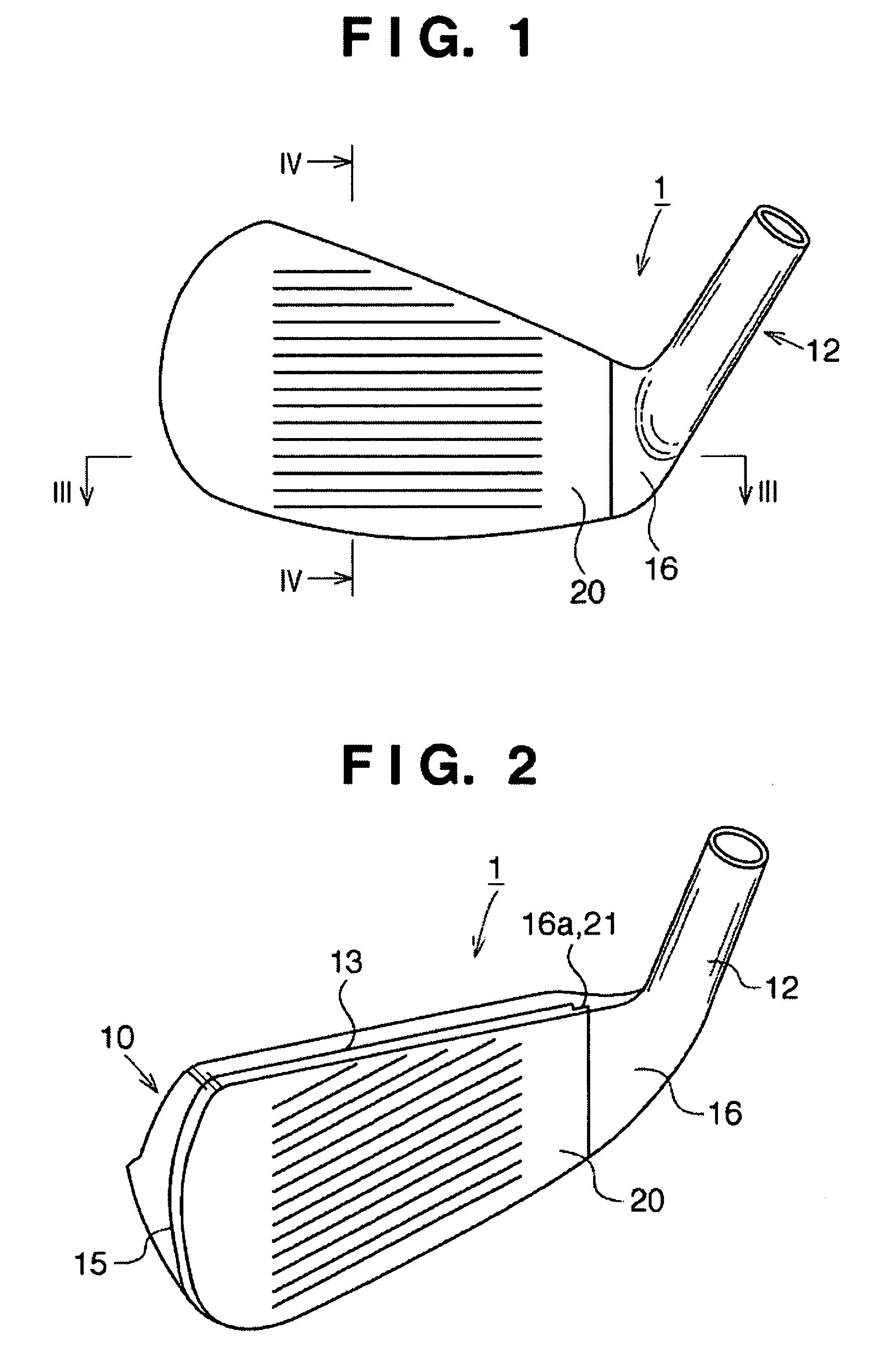
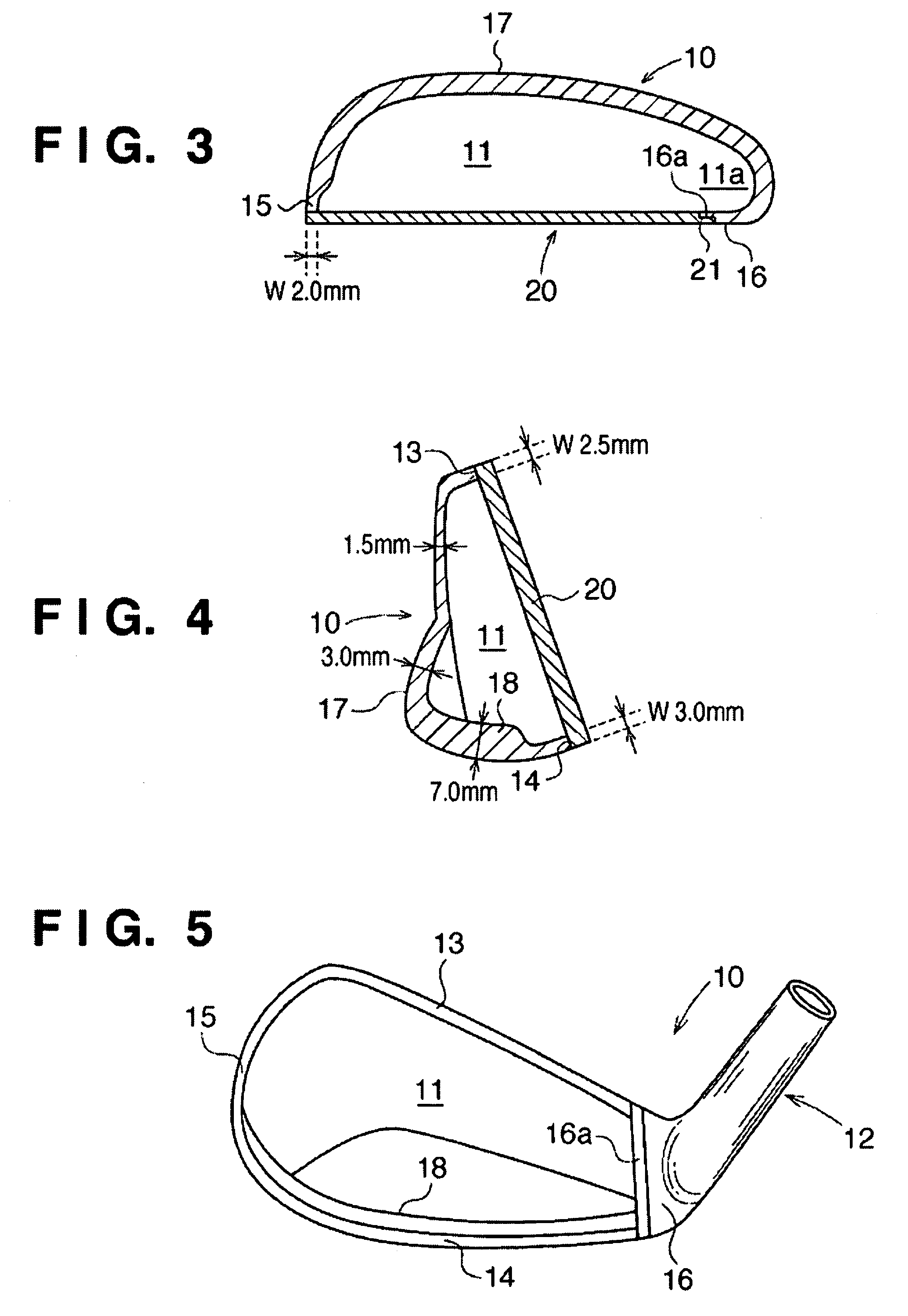
[0020]FIG. 1 is a front view of an iron golf club head 1 according to an embodiment of the present invention. FIG. 2 is a perspective view of the iron golf club head 1. FIG. 3 is a sectional view taken along a line III-III in FIG. 1. FIG. 4 is a sectional view taken along a line IV-IV in FIG. 1. FIG. 5 is a front view of a head main body 10. FIG. 6A is an exploded perspective view of the golf club head 1, and FIG. 6B is a sectional view taken along a line B-B in FIG. 6A.

[0021]The iron golf club head 1 includes the head main body 10 having a concave portion 11 formed in the face side, and a face plate 20 fixed to the head main body 10. The face plate 20 includes a flat front surface (striking face) on which score lines (grooves) are formed.

[0022]A hosel portion 12 is provided in the head main body 10 on the heel side.

[0023]As shown in FIG. 6A, an upper edg...


PUM


Abstract

A golf club head (1) comprises a head main body (10) having a concave portion (11) formed in the face side and a face plate (20) fixed to the head main body (10). The face plate (20) is mounted on the head main body (10) such that a concave step portion (21) engages with a convex step portion (16a) of the head main body (10), and the upper edge portion, lower edge portion, and toe-side edge portion of the face plate (20) abut against edge portions (13), (14), and (15) of the head main body, respectively. The face plate (20) is laser-welded along its perimeter and fixed to the head main body (10).

Description

BACKGROUND OF THE INVENTION[0001]1. Field of the Invention[0002]The present invention relates to an iron golf club head, and particularly to a hollow iron golf club head.[0003]2. Description of the Related Art[0004]As is well known, an iron golf club head includes a face portion having a flat face and a hosel portion which continues to the face portion on the heel side. A shaft insertion hole is provided in the hosel portion. A shaft is inserted into this shaft insertion hole and fixed thereto with an adhesive.[0005]As a hollow iron golf club head, an iron head is described in Japanese Patent Laid-Open No. 2004-105521, which includes a head main body having a concave portion formed in the face side and a face plate fixed to the head main body, and in which the rear surfaces of the upper edge portion, lower edge portion and toe-side edge portion of the face plate are fixed to the front surface of the peripheral portion of the head main body.[0006]In the iron head described in the abo...

Claims


Application Information

Patent Timeline
Patent Type & Authority Patents(United States)
IPC IPC(8): A63B53/04A63B102/32
CPCA63B53/047A63B53/0475A63B53/0466A63B2053/0408A63B2053/0458A63B2053/0491A63B2053/0416A63B60/02A63B53/0408A63B53/0416A63B53/0458A63B53/04A63B53/0433
Inventor TAKECHI, TAKAHARU
Owner BRIDGESTONE SPORTS
Learn More