Endoscope

a technology of endoscope and connection portion, which is applied in the field of endoscope, can solve the problems of transmission cable disconnect, transmission cable connection, circuit board, etc., and achieve the effect of increasing the connection strength of the cable link structure against a pull transmitted by the transmission cabl

Active Publication Date: 2016-07-28
FUJIFILM CORP
View PDF2 Cites 4 Cited by
  • Summary
  • Abstract
  • Description
  • Claims
  • Application Information

AI Technical Summary

Benefits of technology

[0008]The present invention has been made in view of the above circumstances, and an object of the invention is therefore to provide an endoscope in which the connection strength of the cable link structure against a pull transmitted by the transmission cable can be increased.
[0010]The invention can provide an endoscope in which the connection strength of the cable link structure against a pull transmitted by the transmission cable can be increased.

Problems solved by technology

When the transmission cable is pulled in, a problem may occur that peeling occurs at the connection portion of the transmission cable and the circuit board or the transmission cable is disconnected.

Method used


Image

  • Endoscope
  • Endoscope
  • Endoscope

Examples


first embodiment

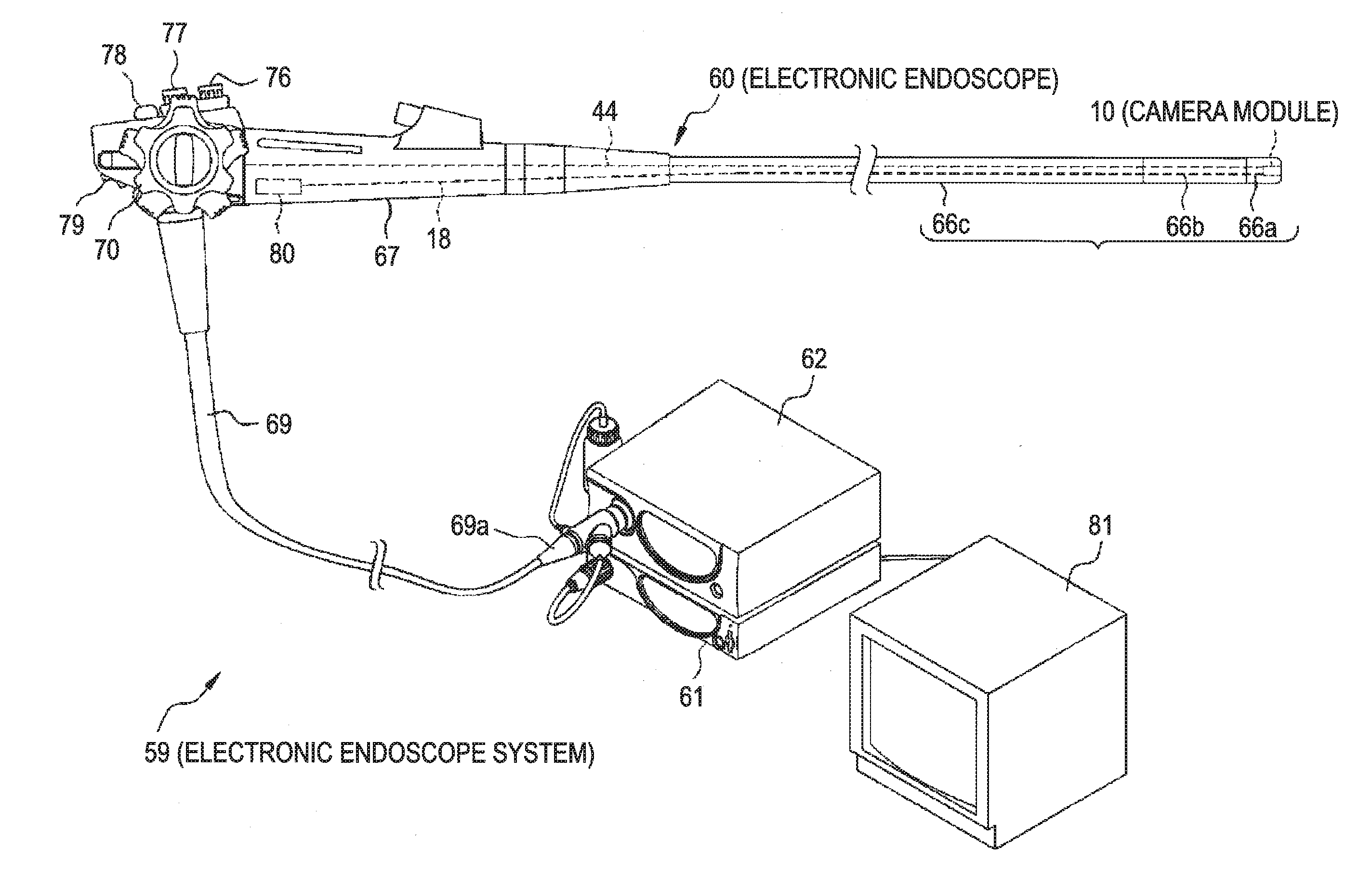
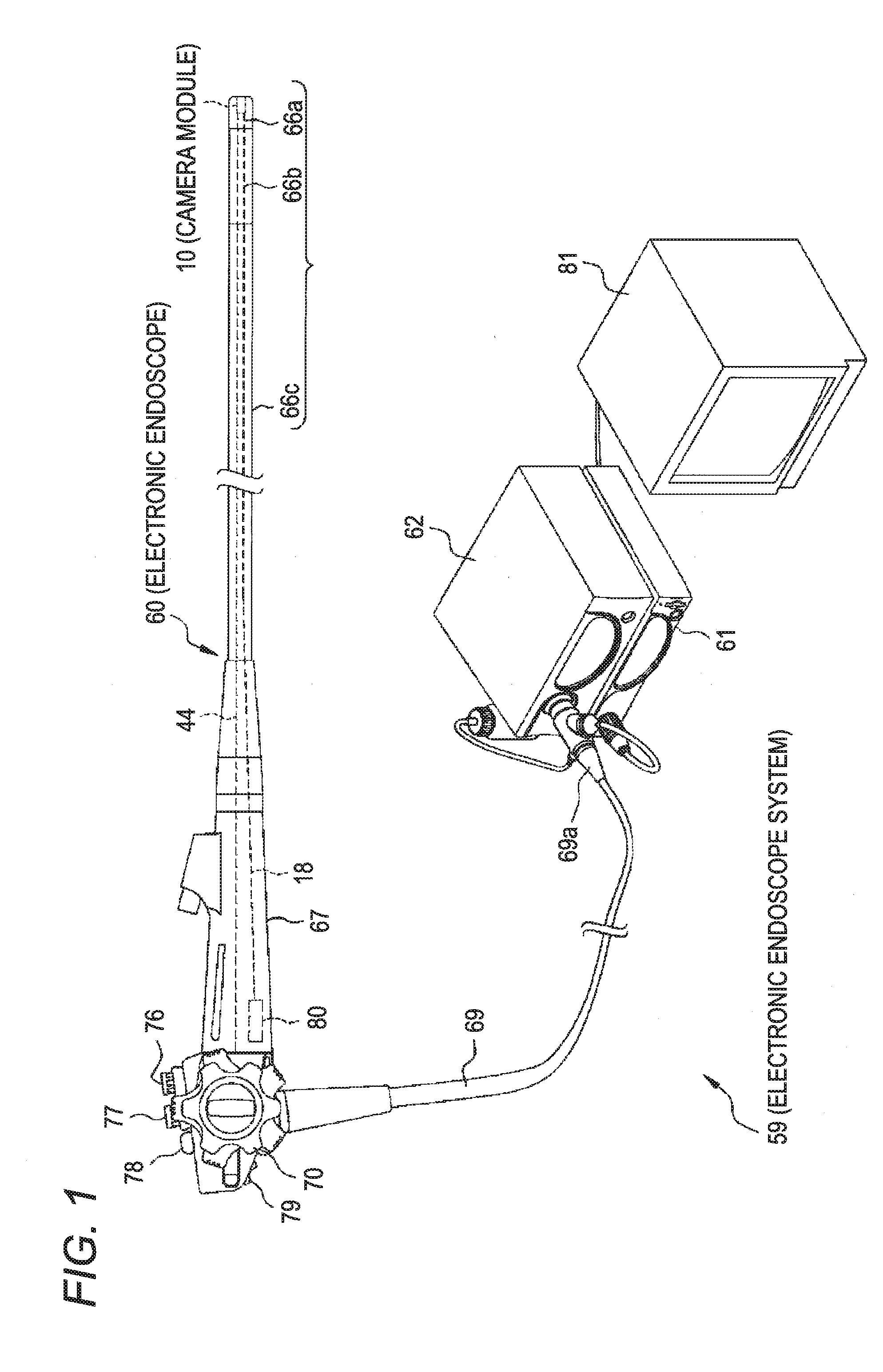
[0047]FIG. 1 is a perspective view showing the configuration of an electronic endoscope system 59 according to the invention. As shown in FIG. 1, the electronic endoscope system 59 is equipped with an electronic endoscope (hereinafter referred to simply as an “endoscope”) 60, a light source apparatus 62, a processor apparatus 61, and a monitor 81.

(Endoscope)

[0048]The endoscope 60 is equipped with a flexible insertion portion 66 to be inserted into, for example, the body cavity of a subject body, a hand manipulation unit 67 which is continuous with a proximal portion of the insertion portion 66, a connector 69a which is connected to the processor apparatus 61 and the light source apparatus 62, and a universal cord 69 which connects the hand manipulation unit 67 to the connector 69a.

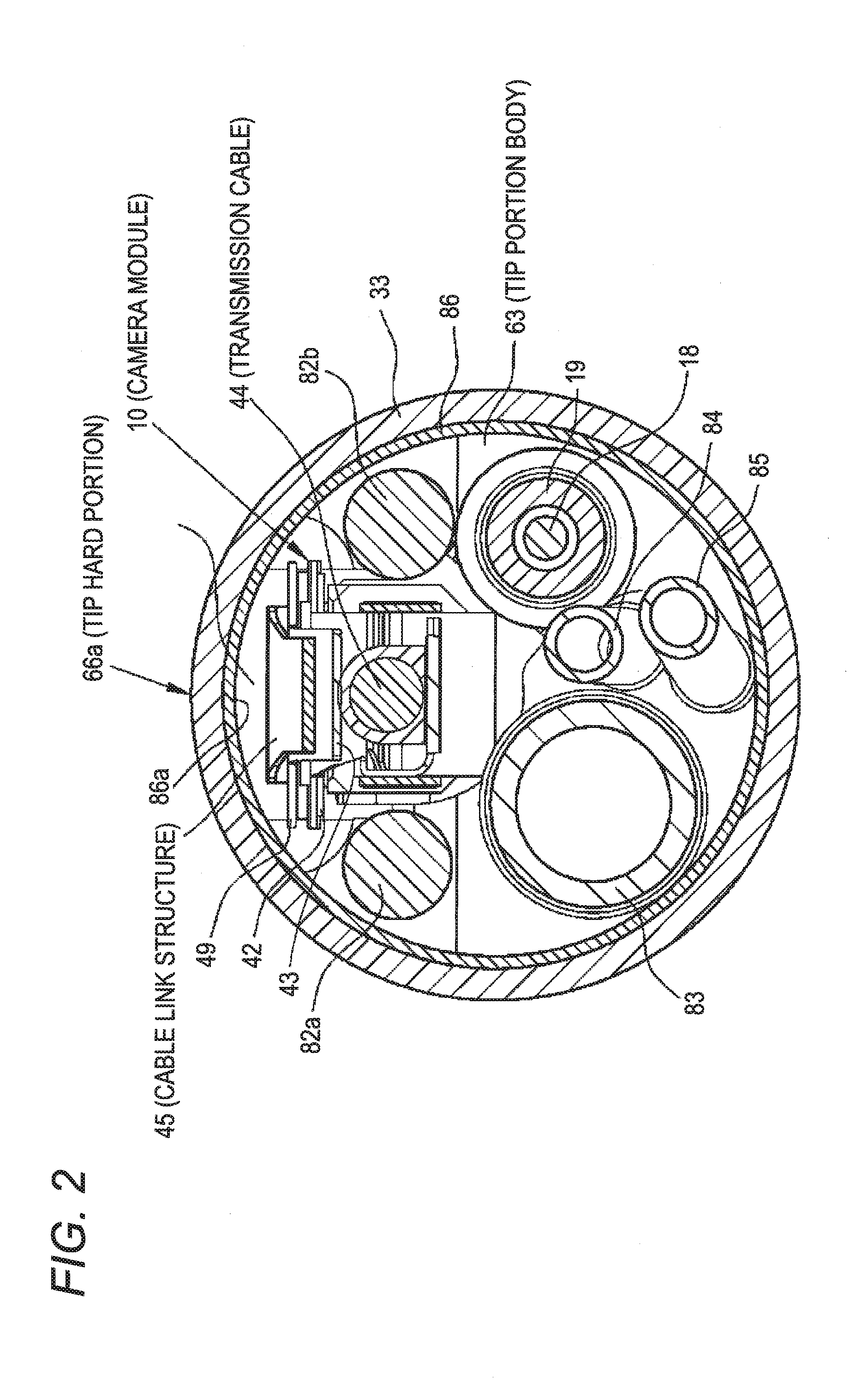
[0049]The insertion portion 66 is composed of a tip hard portion 66a, a curved portion 66b, and a soft portion 66c which are arranged in this order from the tip. FIG. 2 shows a sectional shape of the tip ...

second embodiment

[0087]In the embodiment, as shown in FIG. 2, the cable link structure 45 is disposed in the dead space 87 that is formed between the inner circumferential surface 86a of the tip cylinder 86 and the image area sensor 42. However, as shown in FIGS. 11 and 12, a similar cable link member may be disposed so as to cover the side where the circuit board 43 which is attached to the reflection face 41c of the prism 41 is located. FIGS. 11 and 12 are perspective views showing an appearance of a camera module, excluding the housing 13 etc., according to a

[0088]A cable link structure 55 shown in FIGS. 11 and 12 is composed of an attachment frame portion 55a which is formed by bending both side portions, located at one end, of a generally T-shaped and is made of a metal plate so as to have a U-shaped cross section and a link plate portion 55b which is formed at the other end of the T-shaped metal plate.

[0089]The attachment frame portion 55a is disposed so as to surround the transmission cable 4...


PUM


Abstract

An endoscope includes: a shooting lens unit having a shooting lens and a housing which holds the shooting lens; a prism on which shooting light coming from the shooting lens shines; a prism holding structure which holds the prism and is attached to one end portion of the housing; an image area sensor which is attached to an exit face of the prism; a circuit board which drives the image area sensor; a transmission cable which is electrically connected to the circuit board; and a cable link structure one end portion of which is fastened to the transmission cable and other end portion of which is attached to a body structure having the prism holding structure and the housing, and the other end portion of the cable link structure is formed with a lock portion as defined herein.

Description

CROSS-REFERENCE TO RELATED APPLICATIONS[0001]This application claims the benefit of Japanese Patent Application JP 2015-012554, filed Jan. 26, 2015, and Japanese Patent Application JP 2015-134617, filed Jul. 3, 2015, the entire contents of which are hereby incorporated by reference, the same as if set forth at length.FIELD OF THE INVENTION[0002]The present invention relates to an endoscope.BACKGROUND OF THE INVENTION[0003]Endoscopes have an insertion portion to be inserted into, for example, the body cavity of a subject body. The insertion portion is composed of a tip hard portion, a curved portion, and a soft portion which are arranged in this order from the tip. The tip surface of the tip hard portion is provided with an observation window, illumination windows, a forceps outlet, and an air / water supply nozzle. A camera module and light guides are attached to the inner wall of the tip hard portion at such positions as to correspond to the observation window and the illumination wi...

Claims


Application Information

Patent Timeline
Patent Type & Authority Applications(United States)
IPC IPC(8): A61B1/00A61B1/045A61B1/06H04N7/18
CPCA61B1/00096H04N7/183A61B1/00114H04N2005/2255A61B1/06A61B1/0011A61B1/00124A61B1/045A61B1/051G02B7/18G02B23/243G02B23/2484H04N23/555A61B1/00112A61B1/00119A61B1/00121A61B1/00117
Inventor KITANO, RYOU
Owner FUJIFILM CORP
Why Eureka
Try Eureka