Tire pressure monitoring device

a technology for monitoring devices and tires, applied in signalling/lighting devices, tire measurements, vehicle components, etc., can solve the problems of increasing the number of parts and mounting costs, inconvenient operation, and inability to specify the position of tires, so as to reduce the consumption of electrical power, increase the gain of a reception signal, and reduce the cost

Inactive Publication Date: 2011-09-06
MURATA MFG CO LTD
View PDF30 Cites 24 Cited by
  • Summary
  • Abstract
  • Description
  • Claims
  • Application Information

AI Technical Summary

Benefits of technology

[0016]The communication unit that is disposed in the vehicle can selectively direct reception beams towards the respective tires, and receive radio signals from the pneumatic pressure monitoring units provided at the respective tires. Therefore, it is not necessary to provide an ID to the radio signal from each pneumatic pressure monitoring unit. Even if an ID is provided to each radio signal, the position of each tire does not need to be determined based on the ID. Consequently, even if a tire is replaced, it is possible to determine from which tire mounted at a location of the vehicle a signal is transmitted. In addition, since it is not necessary to individually provide wheel speed sensors near the respective tires, costs are reduced.
[0017]The communication unit may selectively direct a transmission beam to one of the plurality of tires and send a signal to the pneumatic pressure monitoring unit of the tire. In this case, the communication unit receives a signal transmitted from the pneumatic pressure monitoring unit of the tire, so that, only when the signal is transmitted to the pneumatic pressure monitoring unit from the communication unit, the pneumatic pressure of the tire is measured with the pneumatic pressure monitoring unit, and data regarding the pneumatic pressure is sent to the communication unit. Accordingly, since it is not necessary to periodically measure the pneumatic pressure and transmit the pneumatic-pressure data, it is possible to reduce consumption of electrical power of the pneumatic pressure monitoring unit.
[0018]The directivity of the antenna of each pneumatic pressure monitoring unit may be towards the inside in the axle direction of the tire, so that it is possible to increase the gain of a reception signal of the communication unit provided at the vehicle. Accordingly, power consumption of each pneumatic pressure monitoring unit is reduced correspondingly, so that the life of each power supply battery is increased. In addition, unnecessary radiation to the outside of the vehicle is reduced, thereby preventing another vehicle that is traveling adjacent to the vehicle from erroneously receiving a radio signal from any of the pneumatic pressure monitoring devices of the vehicle.
[0019]Since each pneumatic pressure monitoring unit may have a unit arranged to convert an electromagnetic wave into electrical power, the battery that drives each pneumatic pressure monitoring unit can be easily charged. Therefore, it is unnecessary to replace each battery, such that each pneumatic pressure monitoring unit can be semi-permanently used.
[0020]The unit arranged to convert an electromagnetic wave into electrical power of each pneumatic pressure monitoring unit may convert a transmission signal that is transmitted from the communication unit into electrical power, so that it is possible to charge the battery of each pneumatic pressure monitoring unit. In addition, to reduce the size, it is possible to replace each battery by a capacitor and to convert a transmission electromagnetic wave from the communication unit into electrical power, so that each capacitor can be charged with the electrical power. By using the electrical power obtained in this manner, each pneumatic monitoring unit of the corresponding tire can measure pneumatic pressure of the corresponding tire and transmit pneumatic pressure data.

Problems solved by technology

Therefore, it is necessary to register the IDs at a dealer each time the tires are replaced, which is inconvenient to perform.
However, in the tire pressure monitoring device disclosed in Patent Document 2, since the centrifugal force information of each tire is the same when the vehicle is traveling in a straight line or when the vehicle is stopped, the position of each tire cannot be specified.
Therefore, the number of parts and mounting costs are increased.

Method used


Image

  • Tire pressure monitoring device
  • Tire pressure monitoring device
  • Tire pressure monitoring device

Examples


Embodiment Construction

[0038]A tire pressure monitoring device according to a first preferred embodiment will be described with reference to FIGS. 1 to 7.

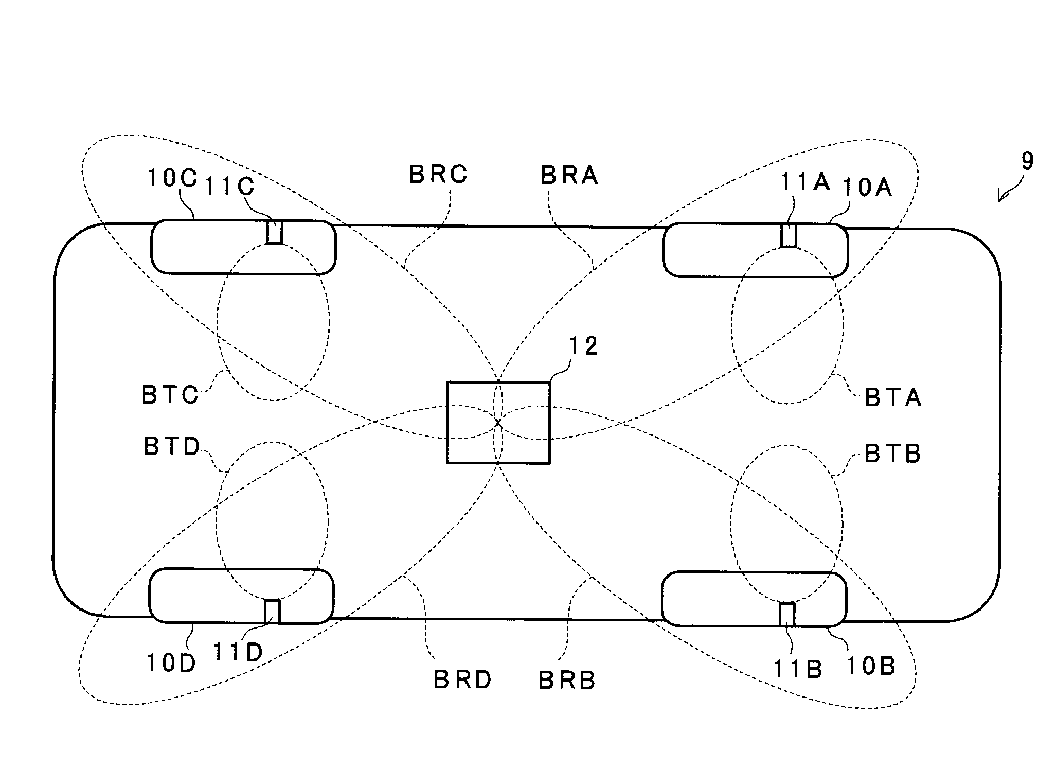
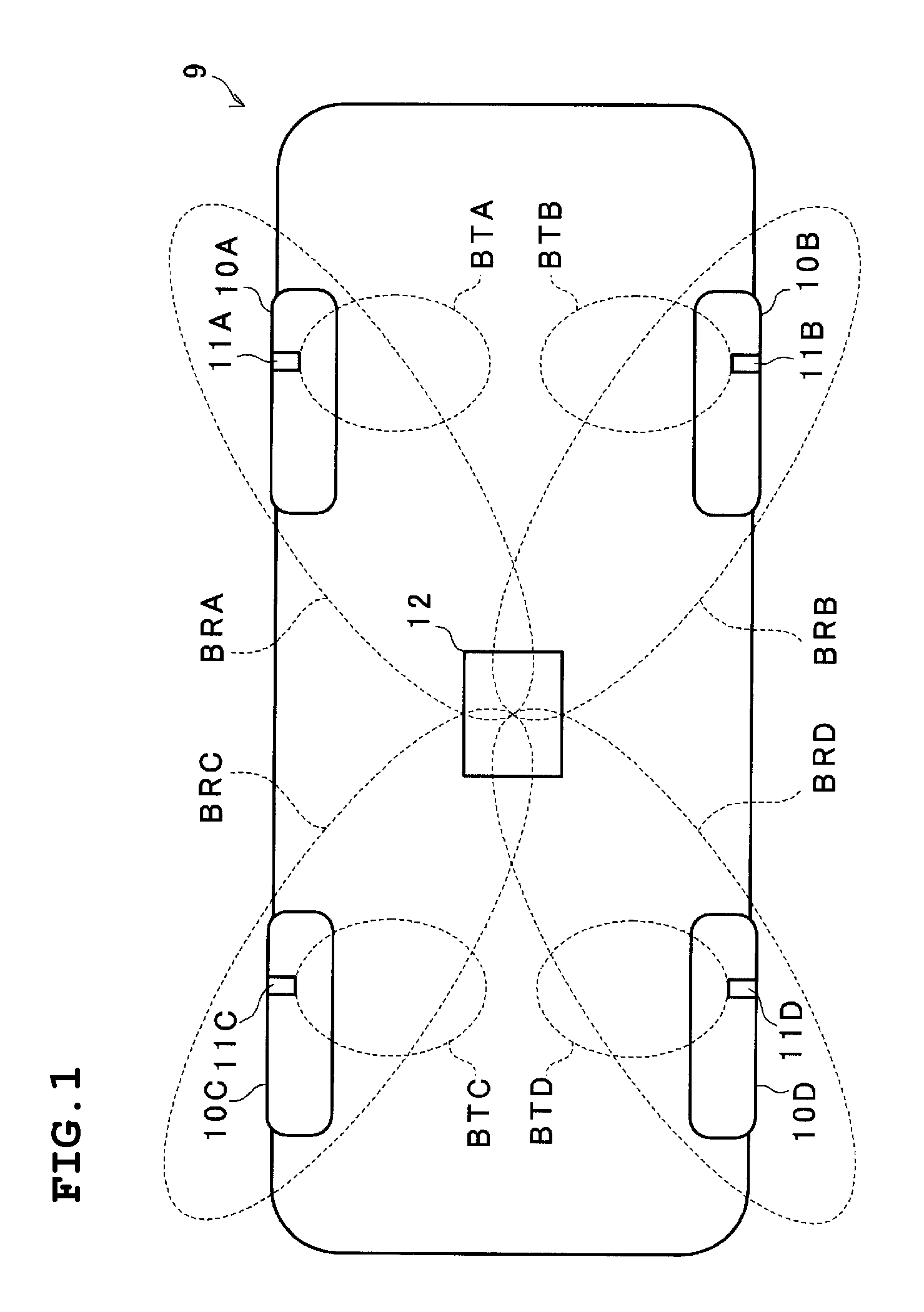
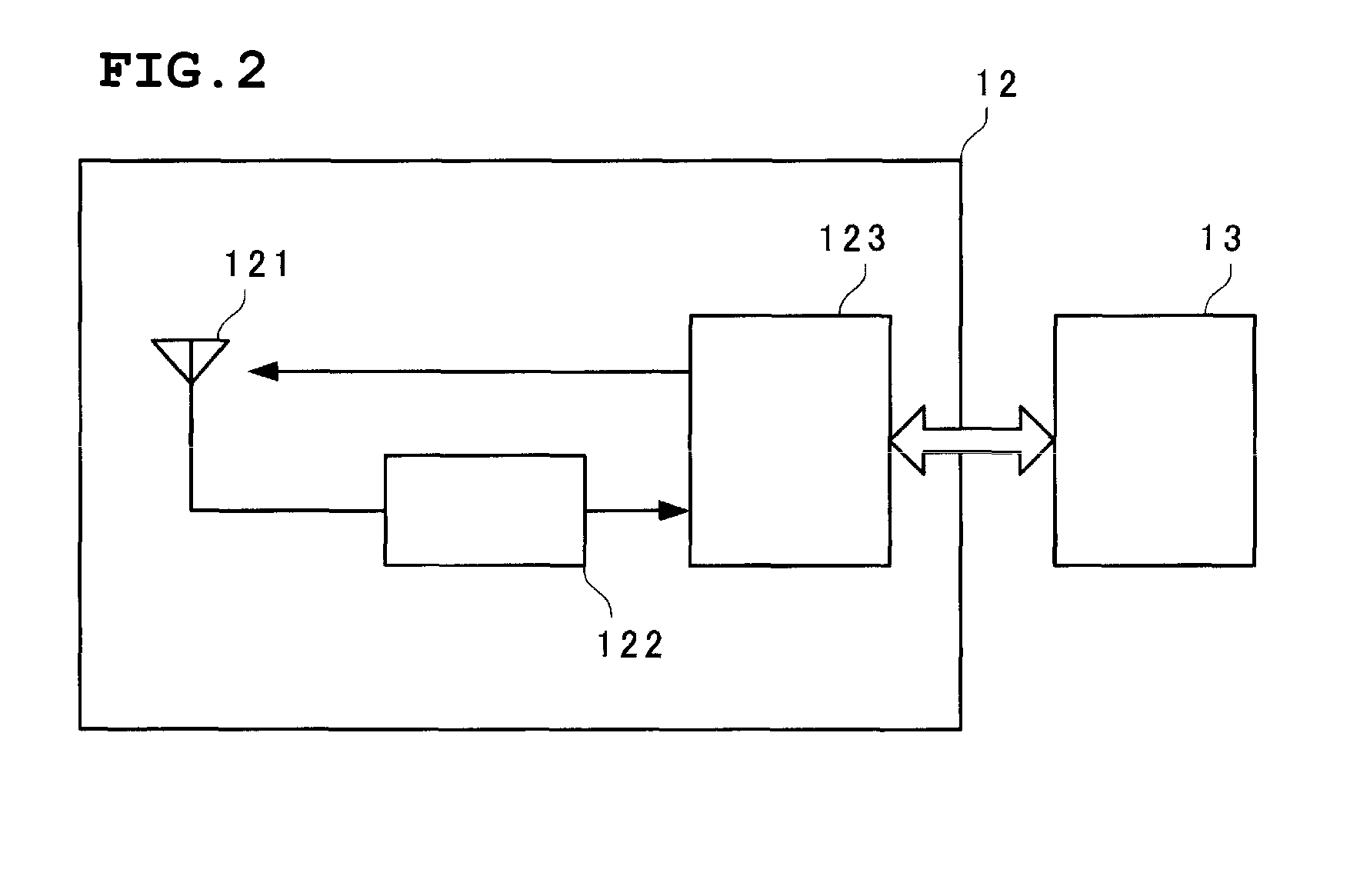
[0039]FIG. 1 is a schematic bottom view of a vehicle in which the tire pressure monitoring device is installed. Four tires 10A, 10B, 10C, and 10D are provided with pneumatic pressure monitoring units 11A, 11B, 11C, and 11D, respectively. A communication unit 12 that receives radio signals from these pneumatic pressure monitoring units 11A to 11D is disposed at substantially the center near the bottom surface of a vehicle 9.

[0040]Each of the pneumatic pressure monitoring units 11A to 11D measures pneumatic pressure and transmits by radio a result of the measurement of the pneumatic pressure. The pneumatic pressure monitoring units 11A to 11D produce respective transmission beams BTA to BTD that are directed inward in axle directions of the respective tires.

[0041]The communication unit 12 selectively produces reception beams BRA to BRD towards the four tir...


PUM


Abstract

Pneumatic pressure monitoring units that measure pneumatic pressures of respective tires and that transmit results of the measurements of the pneumatic pressures from respective antennas by the use of radio signals are provided at the tires, respectively. A communication unit including a beam controller arranged to selectively direct reception beams towards the respective tires is provided at substantially the center near the bottom surface of a vehicle. The antennas of the respective pneumatic pressure monitoring units are constructed so that directivity patterns of transmission beams are directed towards the inside in axle directions of the tires.

Description

BACKGROUND OF THE INVENTION[0001]1. Field of the Invention[0002]The present invention relates to a tire pressure monitoring device that monitors the pneumatic pressure of a plurality of tires of a vehicle.[0003]2. Description of the Related Art[0004]A related tire pressure monitoring device is disclosed in Japanese Unexamined Patent Application Publication No. 9-210827 (Patent Document 1). In the tire pressure monitoring device disclosed in Patent Document 1, as shown in FIG. 15, pneumatic pressure monitoring units A14 are individually installed for respective tires A12, an RF receiver A18 receives pneumatic pressure data, transmitted by radio from each pneumatic pressure monitor unit A14, by one common antenna A16, and a processor A20 distinguishes between characteristic identification codes (ID) of the respective tires to determine from which pneumatic pressure monitoring unit of the tire that the data, such as the pneumatic pressure data, is received.[0005]However, in the tire pr...

Claims


Application Information

Patent Timeline
Patent Type & Authority Patents(United States)
IPC IPC(8): B60C23/00
CPCB60C23/0416B60C23/0444
Inventor MURATA, TSUNEOYAMAGATA, YUKI
Owner MURATA MFG CO LTD
Why Eureka
Try Eureka