Device for filtering a liquefied synthetic material

a technology of synthetic materials and filters, applied in the field of filters of liquefied plastic materials, can solve the problems of expensive manufacture and simple devices

Active Publication Date: 2011-09-13
NORDSON HLDG S A R L & CO
View PDF7 Cites 3 Cited by
  • Summary
  • Abstract
  • Description
  • Claims
  • Application Information

AI Technical Summary

Benefits of technology

[0011]The object of the invention is to achieve the same goals achieved by the conventional prior art devices, but to provide a device that requires less cost to manufacture, i.e., to produce such a device that is less costly, yet provides all the positions of the filter slide that are possible with prior art devices.
[0012]This object of the invention is achieved by-providing a device for filtering liquid plastic having a plurality of split feed channels that feed into a corresponding plurality of filter chambers, whereby a filter slide enables the flow path between on or more of the split feed channels and the respective filter chambers to be regulated. The device according to the invention allows the flow path to be selectively blocked between one or more of the split feed channels, to allow the filter or filters in the corresponding filter chambers to be cleaned, without interrupting the production process. The filter device according to the invention has a housing, a feed channel, a discharge channel and backflow channels. The filter filters and filter chambers are disposed on a filter slide that is slidably positionable, so as to open a flow path from a feed channel to the filter chamber and block the flow path to the backflow channel or, vice versa, to block the flow path between the feed channel and the filter chamber and open the flow path from the filter chamber to the backflow channel. The feed channel is divided into split feed channels, one split feed channel leading to each filter chamber. The diameter of the split feed channel, where it opens into the filter chamber, is reduced, relative to the diameter of the major portion of the split feed channel. In other words, the split feed channel has a major diameter that reduces to a minor diameter, similar to the neck of a bottle, at the end of the channel that opens into the filter chamber. The diameter of the feed channel, that is, before it is split, and the diameter of the discharge channel are the same.
[0014]Another object of the invention, based upon the conventional device described in DE 38 40 904, is to manufacture this device with less cost, i.e., to produce it less expensively, yet to maintain all possible positions of the conventional prior art filter slide.
[0016]It is possible with both configurations to have both filter elements in filtering use at the same time, i.e., with the plastic material flowing through the filters and the filters filtering out contaminants. It is possible with both configurations to slide the filter slides, such that one of the filter elements is blocked from the feed of plastic material and is in contact with the pressure side of the other filter, whereby, however, the flowpath to the backflow channel is still blocked. Finally, it is possible to then slide this filter element in such a way that it comes into contact with the backflow channel, so that the pressure of the other filter is applied to the dirty side of the filter that is to be cleaned. This pressure effectively removes dirt particles from the filter, which are then transported away from the unfiltered side of the filter and carried into the backflow channel.

Problems solved by technology

This makes the device, which is actually a simple design, expensive to manufacture.

Method used


Image

  • Device for filtering a liquefied synthetic material
  • Device for filtering a liquefied synthetic material
  • Device for filtering a liquefied synthetic material

Examples


first embodiment

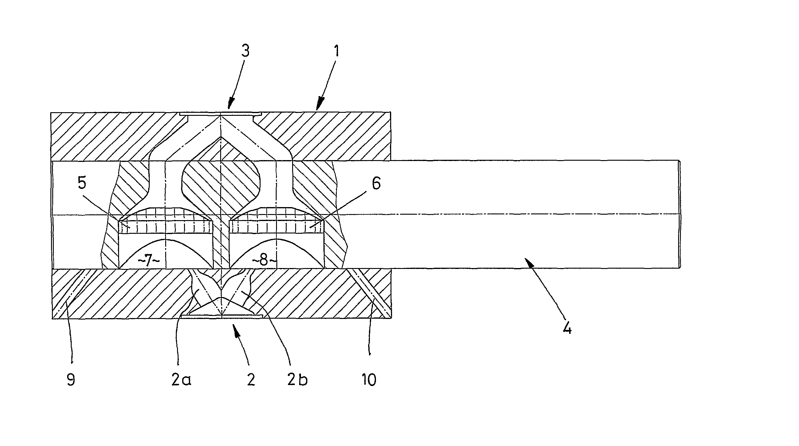
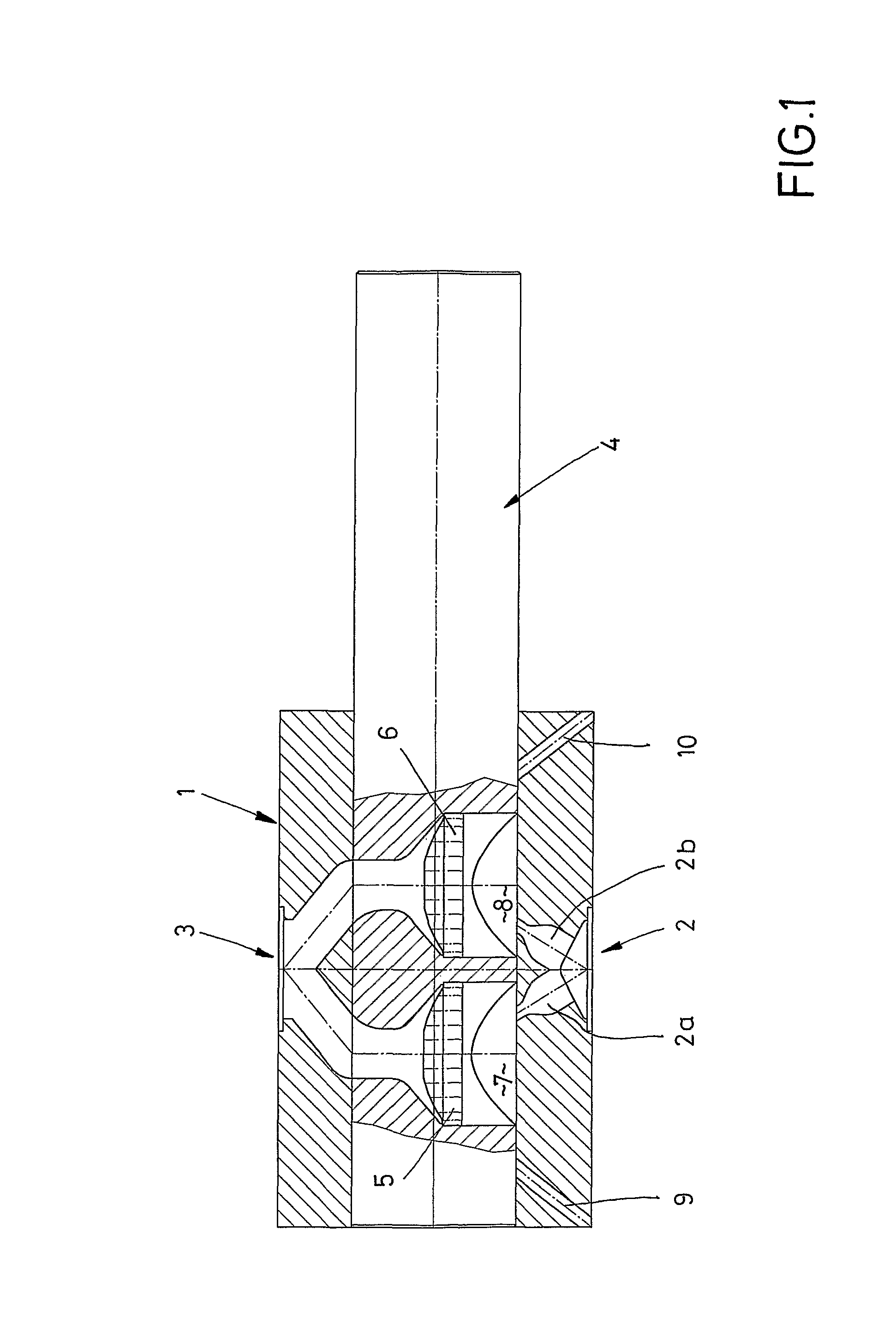
[0027]FIGS. 1 to 4 illustrate a filter device for filtering molten or liquid plastic. The filter device has show a housing 1 with a filter slide 4, also referred to as a filter bolt, slidably disposed therein. The housing 1 has a feed channel 2 for feeding liquefied or molten plastic. The liquefied plastic flows through the filter device and then exits the housing 1 via a discharge channel 3.

[0028]Filter elements 5 and 6 are mounted in respective filter chambers 7, 8 that are provided in the filter slide 4. The plastic material flowing from the feed channel 2 to the discharge channel 3 is filtered and cleansed of impurities in these filter chambers 7, 8.

[0029]Backflow channels 9 and 10 are also provided in the housing.

[0030]The feed channel 2 is divided into a first split feed channel 2A and a second split feed channel 2B. The position of the filter chambers 7,8 relative to the split feed channels 2A, 2B is variable. In the position shown in FIG. 1, these two split feed channels 2A ...

second embodiment

[0035]FIG. 5 shows a device for filtering molten plastic material with a housing 10, a discharge channel 13, a feed channel 12, and two backflow channels 19 and 22.

[0036]The housing 10 has bores 20, 21 for receiving a filter slide 14 and 14A, respectively. Each filter slide 14, 14A is equipped with a filter element 15 and 16, respectively, which is arranged in a respective filter chamber 17 or 18.

[0037]Here, too, a feed channel 12 is divided into two split feed channels 12A and 12B.

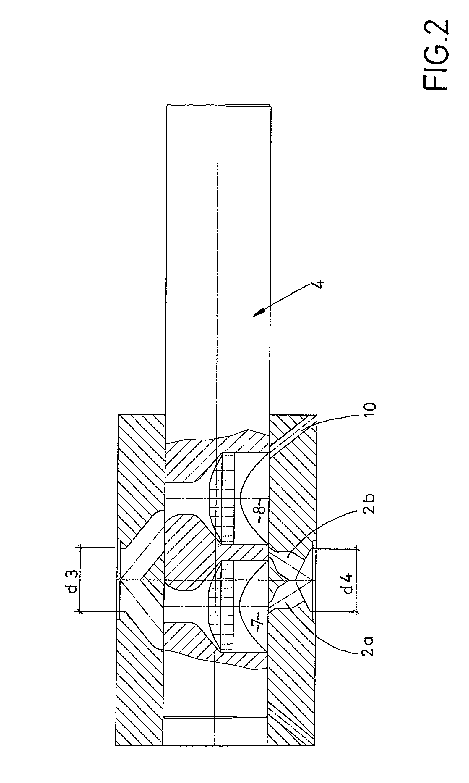
[0038]Again, in this configuration, the first cross-section d1 of the orifice of each split feed channel 12A and 12B is smaller at the entrance into the respective filter chamber 17 and 18, compared to the normal second cross-section d2 of the split feed channels 12A and 12B.

[0039]The orifices of the split feed channels shown in FIGS. 1-5 and also in FIG. 7, are tapered like a bottle neck. It is entirely possible that the filter slide 4, 14, or 14A may simply be appropriately positioned, so as to narrow t...


PUM

PropertyMeasurementUnit
diameter d1aaaaaaaaaa
diameter d2aaaaaaaaaa
diameteraaaaaaaaaa

Abstract

A device for filtering a liquid synthetic material. The device has a housing, a feed channel, a discharge channel, and backflow channels. The feed duct is subdivided into split-feed channels (2A, 2B). The cross-section of the orifice of the split-feed channels, where they open into the filter chambers, is smaller than the normal cross-section of the feed channels.

Description

BACKGROUND INFORMATION[0001]1. Field of the Invention[0002]The invention relates to a device for filtering a liquefied plastic material. More particularly, the invention relates to a device having a plurality of filters and filter chambers. More particularly yet, the invention relates to a device that enables cleaning of a filter without interrupting the production process.[0003]2. Description of the Prior Art[0004]A conventional device is described in DE 102 54 022 B4. The device described in this prior art reference is based on prior art, for example, according to EP 0 798 098 B1.[0005]In the case of the known device according to EP 0 798 098 B1, at least two filter elements are arranged in the flow path of the liquid in corresponding filter chambers. The filter chambers are arranged on a filter slide that is movably positionable transverse to the flow direction. On the filtered side of the filter, a single connecting channel is provided, so as to hydraulically connect the filtere...

Claims


Application Information

Patent Timeline
Patent Type & Authority Patents(United States)
IPC IPC(8): B01D33/48B01D33/44B01D35/22B28B17/02B29C48/03
CPCB29C47/681B29C47/0009B29C48/03B29C48/6912
Inventor WOESTMANN, STEFAN
Owner NORDSON HLDG S A R L & CO
Why Eureka
Try Eureka