Method and apparatus for covering a pressure vessel

a pressure vessel and pressure technology, applied in valve housings, container discharging methods, transportation and packaging, etc., can solve the problems failure of lcf bolts, and failure of pressure vessels with thick flat covers with bores

Inactive Publication Date: 2007-11-29
GENERAL ELECTRIC CO
View PDF9 Cites 2 Cited by
  • Summary
  • Abstract
  • Description
  • Claims
  • Application Information

AI Technical Summary

Problems solved by technology

Covers that incorporate bores tend to be very thick heavy plates of metal.
Pressure vessels with thick flat covers with bores, however, continue to have failures due to stresses.
Such failures include LCF bolt failures that result from the cyclic application of bending stresses.
Such dishing causes a peripheral portion of the cover, through which the bolts pass, to also dish resulting in a bending stress being applied to the bolts.
Such dishing, in the opposite direction than that from the turbine start up condition, results in a bending stress, on the bolts, in an opposite direction.
Consequently, each start up cycle of the steam turbine may result in a fatigue cycle of the cover and the bolts, first in one direction and then in the opposite direction.

Method used


Image

  • Method and apparatus for covering a pressure vessel
  • Method and apparatus for covering a pressure vessel
  • Method and apparatus for covering a pressure vessel

Examples


Embodiment Construction

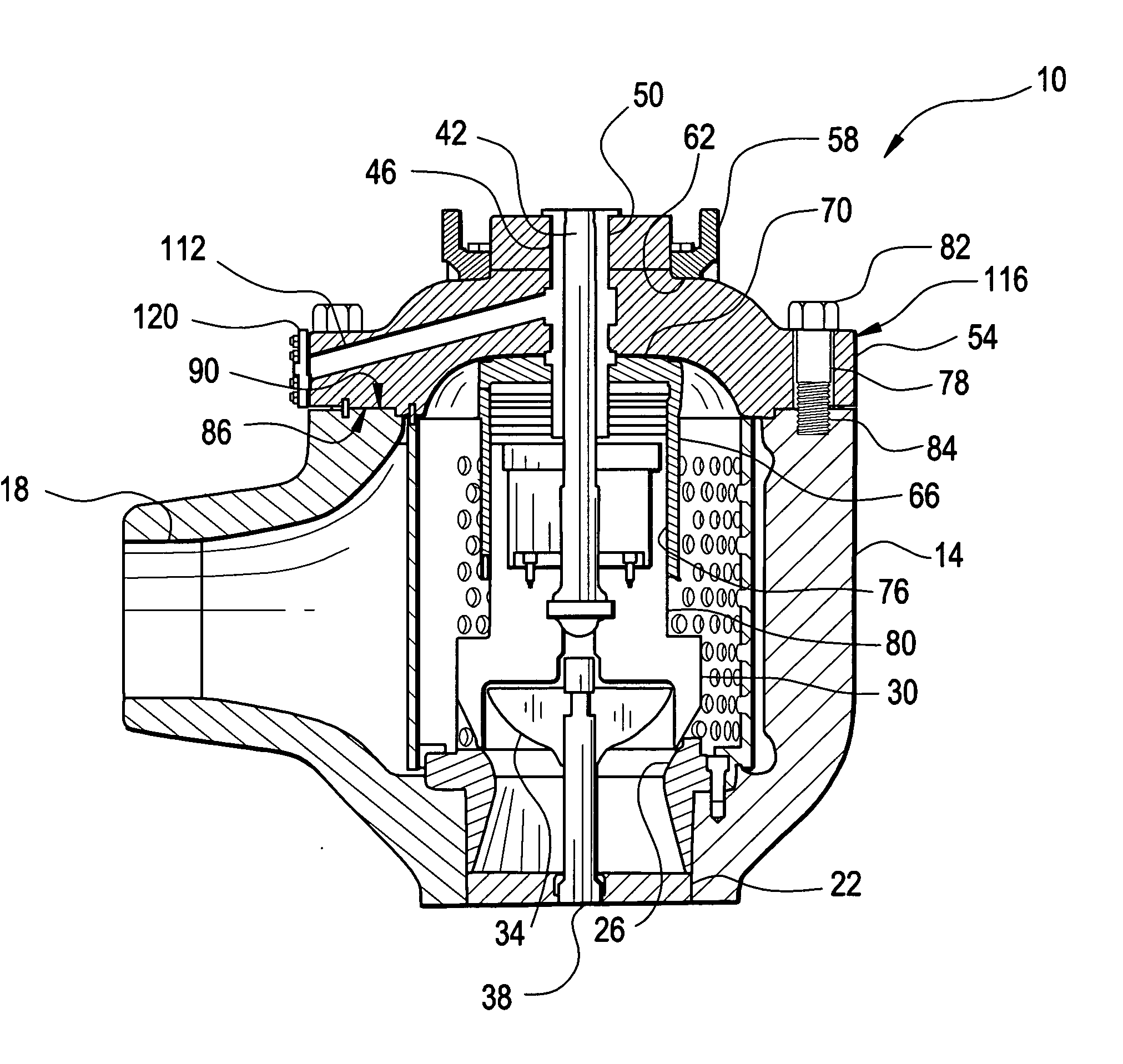
[0014]Referring to FIG. 1, a steam valve assembly in accordance with an embodiment of the invention is generally shown at 10. The valve assembly 10 includes a valve body 14 with an inlet 18 and an outlet 22. A seat 26, sealably attached to the body 14, may receive such as a control valve head 30 or a stop valve head 34. Flow through the valve 10 from the inlet 18 to the outlet 22 flows through the annular opening between the heads 30, 34 and the valve seat 26. Flow of steam is halted when either valve head 30, 34 contacts the seat 26. The stop valve head 34 is actuated through the stop valve stem 38 by a stop valve actuator (not shown). The stop valve is designed to be fully opened or fully closed and may be used as an emergency shut off valve. The control valve head 30 is actuated through control valve stem 42 by a control valve actuator (not shown). The control valve is designed to allow for variable levels of closure depending upon how far the control valve head 30 is from the se...


PUM


Abstract

An apparatus disclosed herein relates to a pressure vessel cover comprising, a periphery of the cover, a first surface of the periphery for sealing on a first side of the cover and a second surface on a second side of the cover opposite from the first side, a third surface on the first side of the cover and located radially inwardly from the periphery, the third surface being displaced axially from the first surface in the direction of the second surface, a fourth surface on the second side of the cover radially inwardly positioned from the periphery, and a bore through the cover in fluidic communication with the third surface and the fourth surface.

Description

BACKGROUND OF THE INVENTION[0001]A chamber that contains a fluid within the chamber at higher pressures than is on an exterior of the chamber is often referred to as a “pressure vessel.” Pressure vessels may be used to house valves, which control the flow of the fluid through the pressure vessel. Such fluid flow may be for the transport of steam, for example, in the case of a steam turbine power plant. Housing the valves within the pressure vessel makes necessary a cover through which access to the valves is possible for purposes of servicing the valves, for example. The cover must form and maintain a seal to the pressure vessel under the various operating conditions that it will be subjected to, such as, elevated pressures and temperatures as well as cycles of varying pressures and temperatures.[0002]Variable flow “control valves” and only fully-opened or fully-closed “stop valves” are commonly used in steam turbine power plants. With the use of these valves it is desirable to have...

Claims


Application Information

Patent Timeline
Patent Type & Authority Applications(United States)
IPC IPC(8): B65D6/00
CPCF16K27/12F16J13/02F17C13/00F17C13/04F17C13/06
Inventor CLARK, BRIAN JOHNWELCH, DAVID ERNEST
Owner GENERAL ELECTRIC CO
Why Eureka
Try Eureka