Electronic device package heat sink assembly

Inactive Publication Date: 2006-12-14
ELECTRO CERAMIC INDS
View PDF16 Cites 6 Cited by
  • Summary
  • Abstract
  • Description
  • Claims
  • Application Information

AI Technical Summary

Benefits of technology

[0007] The present invention finds application in numerous packaging assemblies for microwave devices such as various microwave diodes, oscillators, and amplifier devices, as well as for optical devices including light emitting diodes (LEDs) and other optical RF arrangements for various purposes including (but not limited to) intrusion detection, door openers, police radar detectors, microwave communications, cellular telephone and other applications. In one

Problems solved by technology

One drawback of the cabling is an increase in noise and interference along the path of the tower between the equipment and the horn.
However, one problem with the current package design is that the electronic devices produce a significant amount of heat which needs to be dissipated for the devices to function properly.
Moreover, current designs and methods for securing the devices within a board layout or configuration utilize bolt do

Method used


Image

  • Electronic device package heat sink assembly
  • Electronic device package heat sink assembly
  • Electronic device package heat sink assembly

Examples


Embodiment Construction

[0027] It is to be understood that the figures and descriptions of the present invention have been simplified to illustrate elements that are relevant for a clear understanding of the present invention, while eliminating, for purposes of clarity, many other elements found in typical electronic device or semiconductor package designs and methods of making and using the same. However, because such elements are well known in the art, and because they do not facilitate a better understanding of the present invention, a discussion of such elements is not provided herein. The disclosure herein is directed to all such variations and modifications known to those skilled in the art.

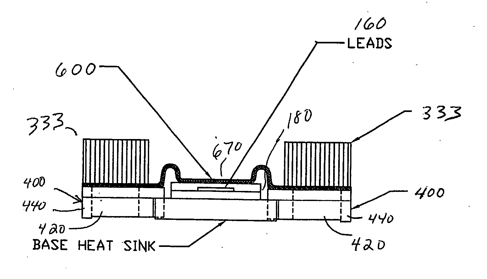
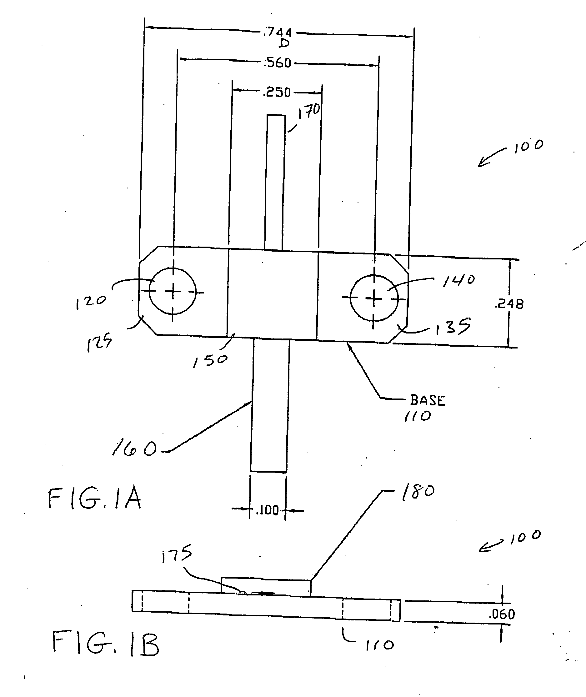
[0028] Referring to FIGS. 1A and 1B, there is shown a standard electronic device package configuration 100 having a base 110 which carries or contains one or more electronic modules or chip sets (e.g. electronic semiconductor chip) 175. The chip set is disposed within a protective cover or lid 180 typically forme...


PUM


Abstract

An electronic package includes a flat base having a notch formed at opposite ends of the base. A clamping mechanism has a boss adapted to the notch for matingly connecting to the base, and includes an aperture for receiving a fastener for securing the package to a substrate or heat sink.

Description

RELATED APPLICATIONS [0001] This application claims priority of U.S. Patent Application Ser. No. 60 / 690,120, entitled ELECTRONIC DEVICE PACKAGE HEAT SINK ASSEMBLY, filed Jun. 13, 2005, the entire disclosure of which is hereby incorporated by reference as if being set forth in its entirety herein.FIELD OF INVENTION [0002] This invention relates generally to heat dissipation in electronic component packages, and more particularly, to an improved arrangement for enabling contact of an electronic package with a heat sink and for accommodating additional packages within a given area. BACKGROUND OF THE INVENTION [0003] There are presently available numerous microwave (and other high frequency) devices which operate over a broad band of frequencies for use in a variety of applications. For example, devices such as Gunn devices, avalanche diodes, amplifiers and other such devices operate over a broad band of frequencies in conjunction with various housings to enable these devices to functio...

Claims


Application Information

Patent Timeline
IPC IPC(8): H05K7/20
CPCH01L23/4006H01L33/64H01L2023/4031H01L2023/405H01L2023/4062H01L2924/0002H01L2023/4081H01L2924/3011H01L2924/00
Inventor SCHLOMANN, HERBERT W.
Owner ELECTRO CERAMIC INDS
Why Eureka
Try Eureka